Ii.installation, Worcester controls – Flowserve I90 Series Intrinsically Safe Modular Accessory System User Manual
Page 3
II.INSTALLATION
A. MOUNTING INSTRUCTIONS
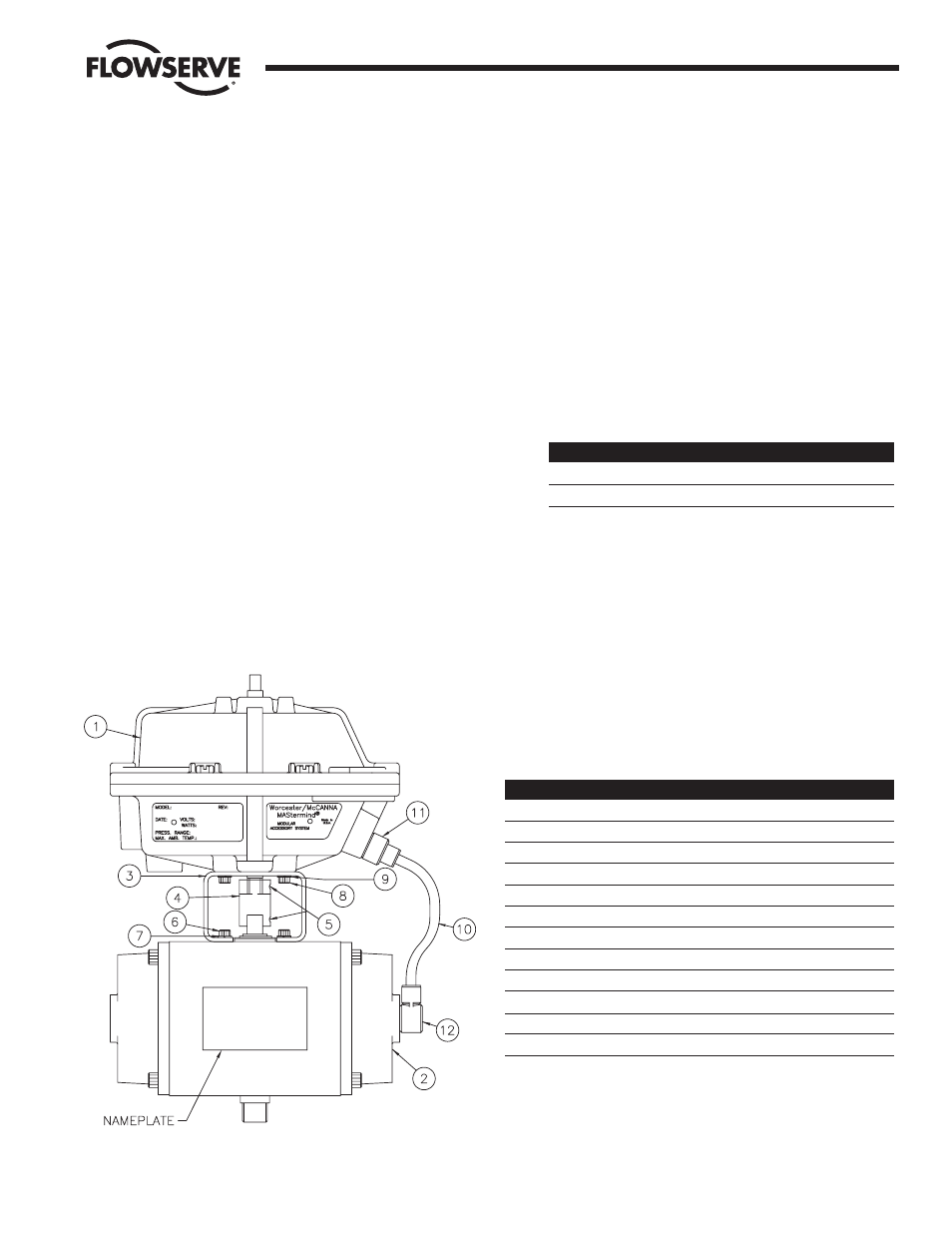
1. Refer to Figure 1. The Series I90 is designed to be mounted
in-line with the major axis of the actuator. The air connections
for the Series I90 should be on the same end as the air
connections for the actuator. The standard 39 actuator has its
air connections on the right-hand end cap as you face the
actuator nameplate. The Series I90 nameplate will be on the
same side as the actuator nameplate.
2. If the actuator is double-acting, rotate the actuator shaft to its
clockwise position. Spring-return actuators will be in this
position already.
3. Place the mounting bracket on the actuator. Secure the
mounting bracket with the four (4) screws and lockwashers
supplied in the kit.
4. Place the coupling over the actuator shaft. (Note: For the 1039
actuator only, shallow slot is placed over the actuator shaft).
The coupling has four (4) threaded holes in it: two are
Z\v"-20
thread for set screws; the other two are #10-32 (located 45
degrees off the center line of the coupling) and are not used.
DO NOT tighten the set screws at this time.
5. Place the Series 90 unit on the bracket while inserting the
shaft into the coupling slot. Be certain the holes in the bracket
and 90 housing are aligned and secure with the four (4)
#10-32 socket head screws and lockwashers provided.
6. The coupling set screws can be tightened after the actuator
has been cycled 90 degrees.
B. AIR CONNECTIONS
1. Series I90 mounting kits contain two (2) elbow “quick”
fittings, two (2) straight “quick” fittings, and one (1) length of
Z\v" O.D. tubing. Single-acting, or “spring-return” assemblies
will use one elbow and one straight fitting. Double-acting
assemblies will use two elbow and two straight fittings. The
length of tubing will be cut to suit the assembly (one piece for
spring-return, two pieces for double-acting).
Refer to Figure 2. Assemble the elbow fitting(s) to the
actuator. Pipe thread sealant may be used on the threads (do
not allow thread sealant to contaminate the internal air
passages of the M.A.S.). Fluoropolymer tape thread sealant
should not be used.
ACTUATOR SIZE
PORT THREAD (NPT)
10 - 20
Z\,"
25 - 40
Z\v"
3. Assemble the straight fitting(s) to the series 90 housing as
shown in Figure 3. The thread sizes are labeled for reference
in the figure. Pipe sealant may be used on the threads (do not
allow thread sealant to contaminate internal air passages of
the M.A.S.). Fluoropolymer tape thread sealant should not be
used.
Flow Control Division
Worcester Controls
WCAIM2033
Intrinsically Safe Modular Accessory System (Series I90)
3
ITEM NO. QTY.
DESCRIPTION
1
1
SERIES I90 - M.A.S.
2
1
SERIES 39 ACTUATOR
3
1
MOUNTING BRACKET
4
2
COUPLING
5
2
SET SCREW
6
4
ACTUATOR MOUNTING SCREW
7
4
ACTUATOR MOUNTING LOCKWASHER
8
4
M.A.S. MOUNTING SCREW
9
4
M.A.S. MOUNTING LOCKWASHER
10
1
Z\v" O.D. X 31" TUBING (CUT BY USER)
11
2
STRAIGHT FITTING
12
2
ELBOW FITTING
Figure 1