Ii. installation, Worcester controls – Flowserve 90 Series Modular Accessory System User Manual
Page 3
II. INSTALLATION
A. Mounting
Instructions
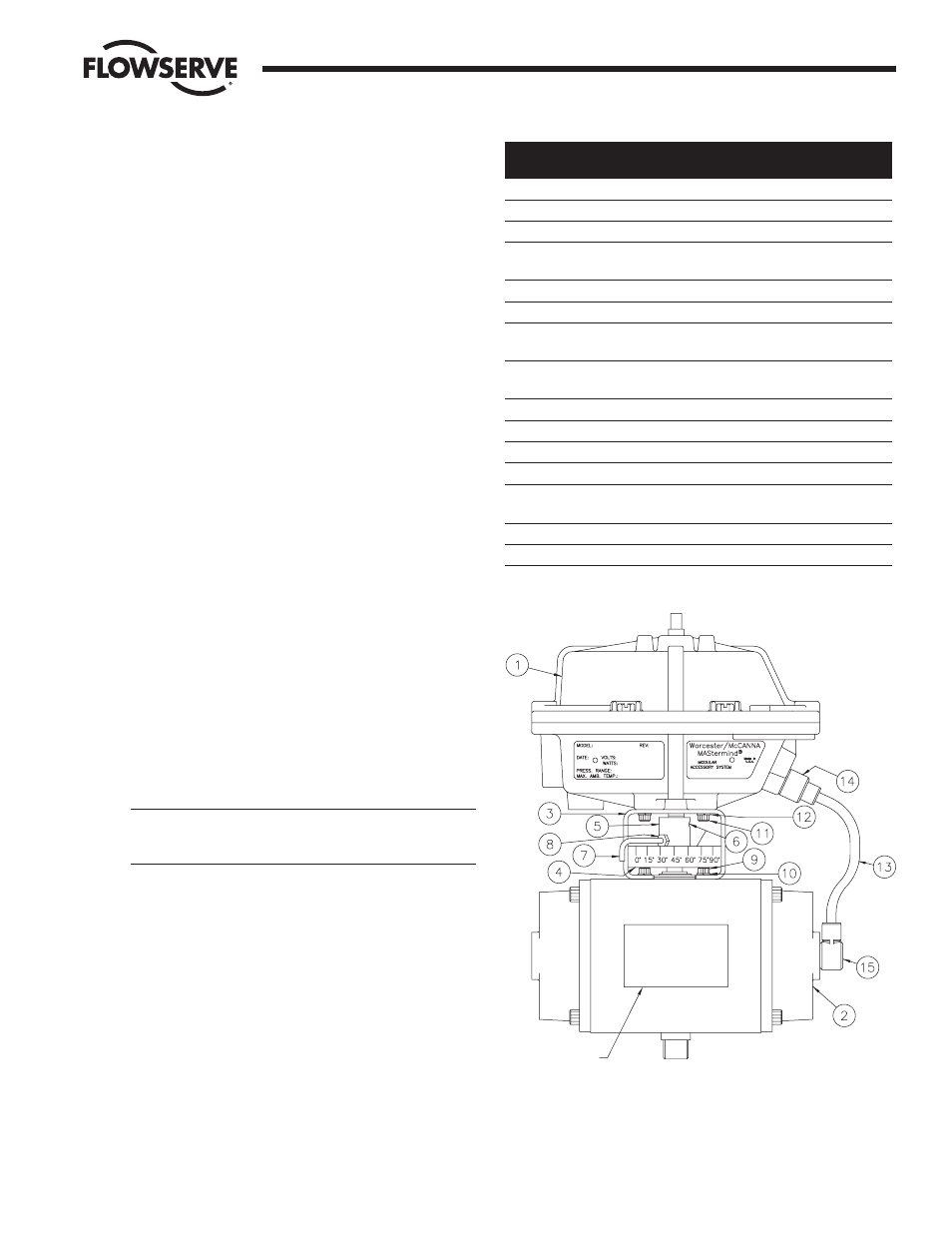
1. Refer to Figure 1. The series 90 is designed to be mounted
in-line with the major axis of the actuator. The air connections
for the series 90 should be on the same end as the air
connections for the actuator. The standard 39 actuator has its
air connections on the right-hand end cap (with the exception
of the line 0539 which has its air connections on the back) as
you face the actuator nameplate. The Series 90 nameplate will
be on the same side as the actuator nameplate.
2. If the actuator is double-acting, rotate the actuator shaft to its
clockwise position. Spring-return actuators will be in this
position already.
3. Place the mounting bracket on the actuator. Brackets to be
used with Series 90 positioner or controller packages may
have an optional indicating scale. This scale can be oriented
on either side of the actuator (depending on customer’s
preference), but normally will be located on the same side as
the actuator nameplate. Secure the mounting bracket with the
four (4) screws and lockwashers supplied in the kit.
4. Place the coupling over the actuator shaft. (Note: For the 05
and 1039 actuators only, shallow slot is placed over the
actuator shaft). Sizes 10-40 couplings have four (4) threaded
holes; two are
¹ ₄-20 thread for set screws and the other two
are #10-32 (located 45 degrees off the center line of the
coupling). The two #10-32 threaded holes must be on the
same side as the indicator scale (if any) on the bracket. The
size 05 coupling has two (2)
¹ ₄-20 threaded holes for set
screws only. DO NOT tighten the set screws at this time.
5. If the mounting kit is for a positioner or controller, an optional
indicating arm and locknut for the coupling may be provided.
If so, install this arm into the coupling and secure with the
locknut. The arm will point down and extend outside the
indicating scale mounted on the bracket.
CAUTION: The actuator is in its clockwise position (per step
#2). The indicating arm must be installed to allow rotation
of the actuator shaft in the counter-clockwise direction.
6. Place the Series 90 unit on the bracket while inserting the
shaft into the coupling slot. Be certain the holes in the bracket
and 90 housing are aligned and secure with the four (4) #10-
32 socket head screws and lockwashers provided.
7. The coupling set screws can be tightened after the actuator
has been cycled 90 degrees.
Item
No.
Qty
Description
1
1
Series 90 – M.A.S.
2
1
Series 39 Actuator
3
1
Mounting Bracket
4
1
Indicating Scale – Optional
(Positioner/Controller Only)
5
2
Coupling
6
2
Set Screw
7
1
Indicating Arm – Optional
(Positioner/Controller Only)
8
1
Locking Unit – Optional
(Positioner/Controller Only)
9
4
Actuator Mounting Screw
10
4
Actuator Mounting Lockwasher
11
4
M.A.S. Mounting Screw
12
4
M.A.S. Mounting Lockwasher
13
1
¹ ₄" O.D. X 31" Tubing
(Cut by User)
14
2
Straight Screw
15
2 Elbow
Fitting
07334-F
Modular Accessory System (Series 90)
3
Flow Control Division
Worcester Controls
Figure 1
Nameplate