Worcester controls – Flowserve 90 Series Modular Accessory System User Manual
Page 4
4
Modular Accessory System (Series 90)
07334-F
B. Air Connections
1. Series 90 mounting kits contain two (2) elbow “quick”
fittings, two (2) straight “quick” fittings, and one (1) length of
¹⁄₄" O.D. tubing. Single-acting or spring-return assembles will
use one elbow and one straight fitting. Double-acting
assemblies will use two elbow and two straight fittings. The
length of tubing will be cut to suit the assembly (one piece for
spring-return, two pieces for double-acting).
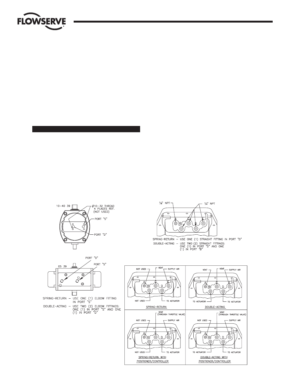
2. Refer to Figure 2. Assemble the elbow fitting(s) to the
actuator. Pipe thread sealant may be used on the threads (do
not allow thread sealant to contaminate the internal air
passages of the M.A.S.). Fluoropolymer tape thread sealant
should not be used.
Actuator Size
Port Thread (NPT)
05 – 20
¹⁄₈"
25 – 40
¹⁄₄"
3. Refer to Figure 3. Assemble the straight fitting(s) to the
Series 90 housing as shown in Figure 3. The thread sizes are
labeled for reference in the figure. Pipe sealant may be used
on the threads (do not allow thread sealant to contaminate the
internal air passages of the M.A.S.). Fluoropolymer tape
thread sealant should not be used.
4. Cut the tubing provided to as short a length as possible that
will still reach comfortably from the Series 90 unit to the
actuator. On double-acting versions, the tubes run parallel to
each other and do not cross. The operation of the actuator
can be reversed by reversing the location of the tubes at the
actuator. Connect the tubes to their respective actuator and
series 90 ports (ref. Figures 2, 3 and 4).
5. Refer to Figure 4 for a diagram of the Series 90 air
connections in each of its four (4) configurations.
a. Connect the supply air for the actuator (80 psi
nominal/100 psi maximum) to the location labeled
“SUPPLY” in the appropriate sketch.
b. Locations labeled “VENT” may be fitted with a porous
muffler (or other fitting if desired) to reduce exhaust noise.
Air must be allowed to flow freely from these ports. “VENT”
locations must not be plugged under any circumstances.
c. Ports labeled “NOT USED” must remain plugged with the
stainless steel pipe plugs provided.
Flow Control Division
Worcester Controls
Figure 2 – Actuator Fitting Locations
Figure 3 – M.A.S. Fitting Locations
Figure 4 – Air Connections for All M.A.S. Configurations