5 geometry of setup – Fluke Biomedical 35080M User Manual
Page 14
Operation
Oscilloscope Zero and Offsets
2
2-3
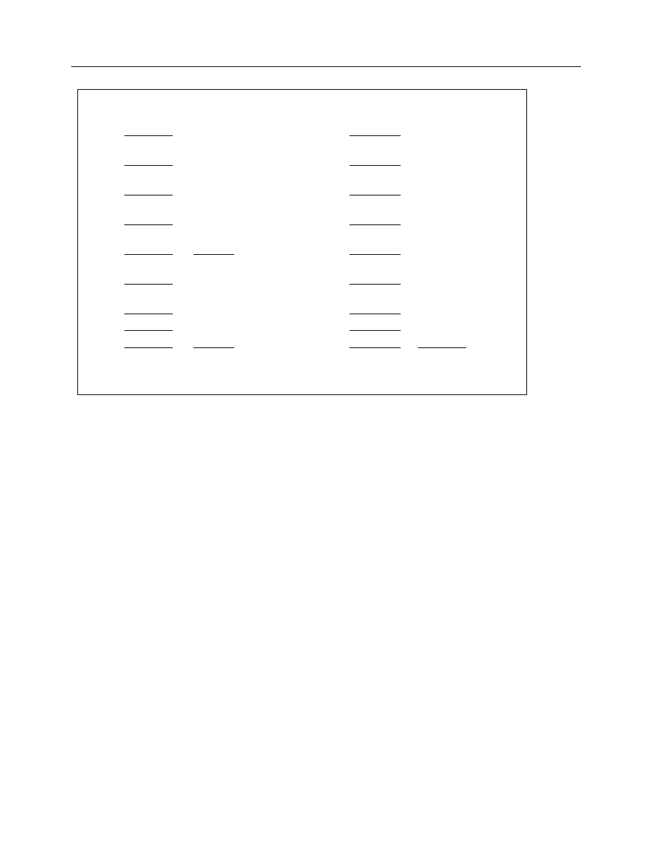
1A)
1B)
120 kV
160
kV
110 kV
150
kV
100 kV
140
kV
90 kV
130
kV
80 kV
CAL at 80
120
kV
70 kV
110
kV
60 kV
100
kV
50 kV
90 kV
40 kV
ZERO at 40
80 kV
CAL at 80
Sensitivity 10 kV/div
Scope setting 0.1 V/div
Sensitivity 10 kV/div
Scope setting 0.1 V/div
Figure 2-1A and 1B.
Suggested Oscilloscope Settings for Use with the Wide Range Filter Pack
(37617)
As an alternative to reading directly in kV, the output of the Model 35080M kVp Divider may be read
directly in volts. The formula below is used to calculate the kV:
kV = Model 35080M voltage x 100 + ZERO kV
Example: A peak voltage of 0.300 volts is read. The ZERO kV of the Wide Range Filter Pack (37617) is
40 kV. Therefore:
kV = 0.300 x 100 + 40
= 30 + 40
= 70 kV
2.5 Geometry of Setup
The filter pack is aligned on the beam center, with the long axis of the Model 35080M kVp Divider
perpendicular to the X-ray tube axis, and the beam normal to the tabletop (see Figure 2-2). The X-ray
beam must be large enough to cover the active area of the filter pack. Distance is not critical, but a 22-
inch distance from focal spot to kVp divider is suggested.
The kVp divider must be inverted for under-table X-ray head evaluation (refer to Figure 2-3). Again, the
filter pack should be on beam center, perpendicular to the axis of the X-ray tube and the beam normal to
the table. The beam area must be large enough to cover the active area of the filter pack.