Fronius Personal Display User Manual
Page 10
6
Erecting/connec-
ting the antenna
If using a Fronius IG 400/500 please install the antenna on the wall. The Cable extension
which is necessary is available at Fronius.
Fronius
IG 400/500
Installing the
display card in
Fronius IG / IG
Plus
(continued)
NOTE! The following points should be borne in mind when installing the display
card:
-
Only install the display card in the „Option 1“, „Option 2“ or „Option 3“ slots
-
Under no circumstances should it be installed in the slot on the extreme
left, which is labelled ENS
7.
Close the housing
8.
Connect AC and DC lines to Fronius IG / IG Plus
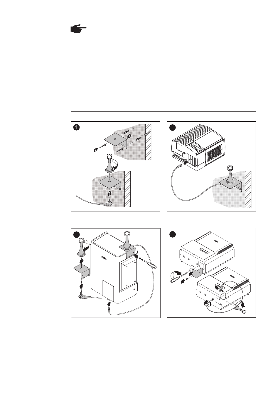
The antenna is supplied with a 2 m (6.74 ft) connecting cable. If the Fronius IG / IG Plus
is installed in a location that is shielded from radio waves, this cable allows the antenna
to be erected where it can receive radio waves.
FRONIUS IG Indoor wall mounting and connection:
2
1
1
4
1
2
3
5
FRONIUS IG Outdoor/FRONIUS IG US installation:
1
4
5
3
1
2
Important! Use the previously removed original housing screw to screw the antenna
mounting bracket onto the housing.