Controls and connections – Fronius Acctiva 12-20 User Manual
Page 30
2
Controls and connections
Controls and
connections
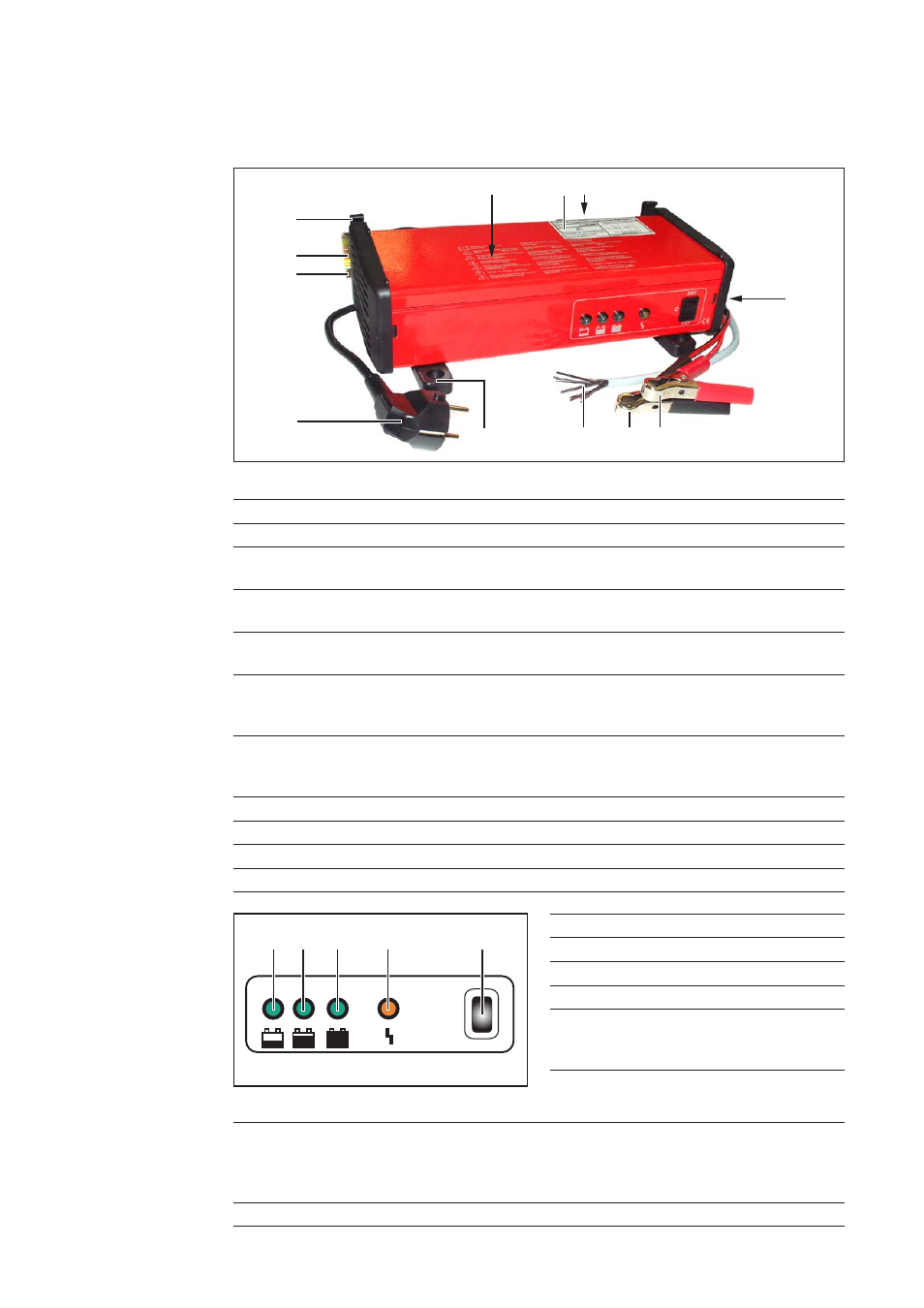
Fig. 2 Controls and indicators
(12)(13) (14)
(15)
(16)
(1) Mains connection
(2) Wall mounting device
(3) Wall bracket option (42,0200,8891)
with DIN rail TS 35 (EN 50022)
(4) Holder for mains cable and charger leads
saves space when stowing mains cable and charger leads
(5) If the protection against undesired starting option is in use, sticker with
circuit diagram
(6) Option for protection against undesired starting
-
1-pin with change-over contact (4,010,291)
-
2-pin with change-over contact (4,100,285)
(7) Mode selector switch (inside the housing)
for selecting the battery types „wet“ or „GEL“ and external power supply/charge
deep-discharge battery mode
(8) Charging terminal (+) (red)
(9) Charging terminal (-) (black)
(10) Control lines (if option for protection against undesired starting in use)
(11) Floor installation option (4,100,314)
(12) Battery charging indicator
(13) „Final charging“ indicator
(14) Conservation charging indicator
(15) Error indicator
(16) Stop button (Acctiva 12/20, 24-10)
pressing the Stop button de-energises
the charging terminals
(16) Selector switch 12 / O / 24 (Acctiva 12/24-20 only)
12 V
for charging 12 V batteries
O
Ready (de-energised charging terminals)
24 V
for charging 24 V batteries
(17) Warning notices affixed to the charger
(1)
(2)
(3)
(4)
(5)
(7)
(8)
(9)
(10)
Fig. 1 Controls and connections
(6)
(11)
(17)