Mounting – GAI-Tronics 702-002 Single Party 24 V DC Amplifier Enclosure User Manual
Page 4
Pub. 42004-147H
Model 702-002, 732-102, and 733-002 24 V DC Single-Party Amplifier Enclosures
Page 4 of
12
f:\standard ioms - current release\42004 instr. manuals\42004-147h.doc
08/13
Mounting
The Model 732-102 Weatherproof Metallic Enclosure is supplied with pre-drilled cable openings and
conduit hubs with top and bottom cap plugs in place to prevent contamination. The Model 702-002
Indoor Enclosure and the Model 733-002 Weatherproof Non-metallic Enclosure are not supplied with
conduit or cable openings.
Drill or punch these openings using the template supplied before mounting the enclosure. The
recommended cable entry point is via the bottom of the enclosure near the rear surface to prevent
moisture from dripping onto the terminals or PCBAs. A secondary location for cable entry is in the top
of the enclosure toward the sides. Avoid the top center, as it may interfere with the plug-in amplifier
receptacle. Under no circumstances should cable entries be made in the side of the enclosure as this may
interfere with the installation of the plug-in amplifier.
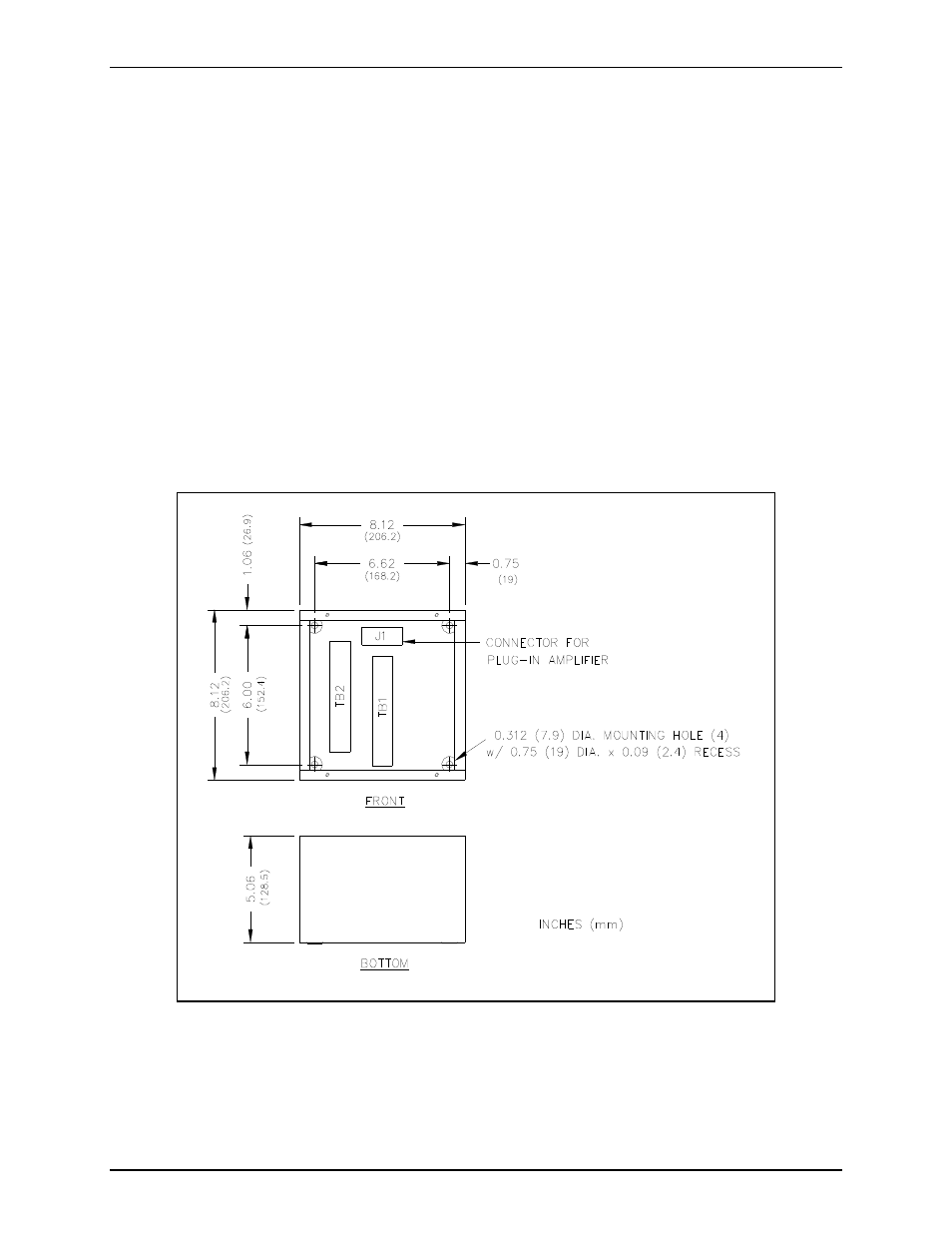
For specific details including mounting hole dimensions, refer to Figure 1 for the Model 702-002 Indoor
Enclosure, Figure 2 for Model 733-002 Weatherproof Non-metallic Enclosure, and Figure 3 for the
Model 732-102 Weatherproof Metallic Enclosure. When mounting the enclosure, use caution to avoid
damaging the terminal blocks inside. The suggested mounting height for all station enclosures is
54 inches (137 cm) up to the centerline of the enclosure.
Figure 1. Model 702-002 Indoor Enclosure Mounting Details