Line balance assembly adjustment, Specifications – GAI-Tronics 305-001 Line Balance Assembly User Manual
Page 2
Pub. 42004-165E
Model 305-001 Line Balance Assembly
Page 2 of 2
f:\standard ioms - current release\42004 instr. manuals\42004-165e.doc
04/13
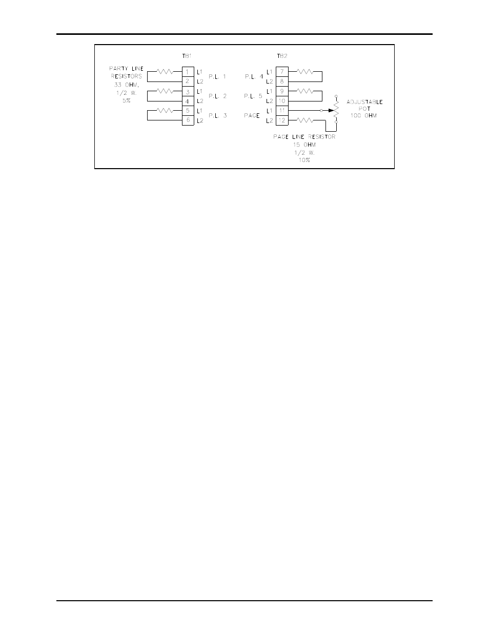
Figure 1. Line balance assembly terminal block connections
Line Balance Assembly Adjustment
1. Remove the line balance assembly cover to expose the line balance control.
2. To set the control for proper page circuit loading, lift the handset from the adjacent handset station
and press the push-to-page button. From a normal speaking distance (approximately 1/2 inch), blow
steadily into the handset microphone and adjust the control to minimize receiver sidetone.
(Sidetone is the amount of signal transmitted from the microphone of a handset to the ear piece, i.e.,
how loudly the speaker hears their own voice.)
N
OTE
: This adjustment needs to be made only at the initial installation of a system. However, if
more than 10 speaker amplifiers are added or deleted, repeat the adjustment of page circuit loading.
3. After final adjustment, replace the cover and secure with four mounting screws to discourage
tampering by unauthorized personnel and prevent entry of contaminants.
For more detailed system installation information, please refer to GAI-Tronics Pub. 42004-139 for 700
Series 120 V ac systems, or Pub. 42004-140 for 700 Series 24 V dc systems.
Specifications
Wiring ..................................................... The assembly contains a barrier-type terminal strip to which field
wiring connections are made to page and party line circuits.
Mounting ................................................. Mounting lugs or supported by a 1-inch conduit nipple connected
between the conduit hub and the handset station.
Enclosure ................................... Cast aluminum two-gang outlet box with cast, dust-tight aluminum cover
Control ......................................................................... Line balance control is provided for the page circuit
Finish .............................................................................................................................. Aluminum or epoxy
Dimensions ................................................... 5.30 H
4.60 W 2.25 D inches (134.6 116.8 57.2 mm)
Shipping weight ....................................................................................................................... 2 lbs. (0.9 kg)
Approvals
NRTL Listed for USA and Canada ......................................................... Class I, Div. 2, Groups A, B, C, D;
Class II, Div. 2, Groups F and G; Class III, Div. 2
CE Mark