GAI-Tronics Call/Talk Installation of Call/Talk Systems User Manual
Page 2
Pub. 42004-251A
Installation of Call/Talk Systems
Page: 2 of 9
\\s_eng\gtcproddocs\standard ioms - current release\42004 instr. manuals\42004-251a.doc
08/05
STEP 1 - Station and Speaker Amplifier Enclosure Mounting
Each Call/Talk station consists of an enclosure, a cover plate, a power supply, and a speaker amplifier
module. Each enclosure provides a terminal strip for connecting interstation cable. The 16-gauge cold-
rolled steel/light gray enamel enclosures use internal screw-type barrier terminal blocks. The suggested
mounting height for all station enclosures is 54 inches (137 cm).
STEP 2 - Line Balance Assembly Mounting
One line balance assembly is required for each communications system. The function of the line balance
assembly is to properly load the page and the party line circuits. There are three primary considerations in
determining the location of the line balance assembly:
• It should be near the electrical center of the system.
• It should be adjacent to the indoor station in a relatively quiet area.
• It should be no more than 5,250 feet (1600 m) from the most distant station when using GAI-Tronics
standard cable. For larger systems or when non-standard cable is to be used, please contact a
GAI-Tronics representative for further information.
The line balance assembly has one electrical adjustment that must be made while using a station (see the
Step 5 - Checkout and Adjustment section).
The preferred mounting method is to suspend the assembly by a 1-inch conduit nipple (not supplied) from
the lower side of an indoor wall station. The terminal blocks of the line balance assembly and the
associated indoor wall station must be connected by one twisted pair for the page circuit and one similar
pair for each party line. Refer to the typical wiring diagrams on pages 8 and 9 for the connections between
the Model 305 Series Line Balance Assembly and the wall station enclosure.
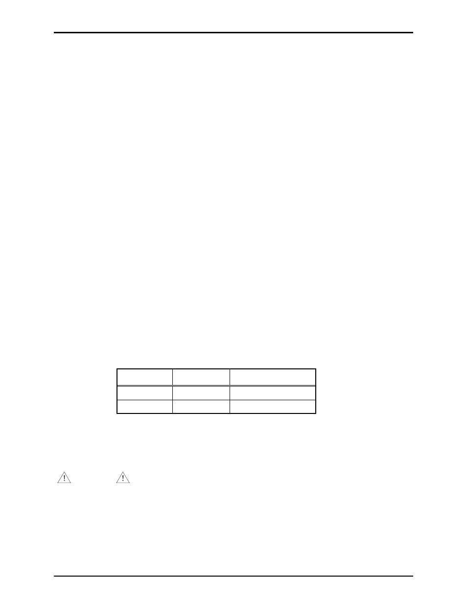
STEP 3 - Inter-station Conduit and Cable Installation
Generally, interstation cables are installed in cable trays or conduit. To help determine the required conduit
sizes, the outside diameters of the GAI-Tronics cables discussed in this manual are listed in the following
table:
Cable
Conductors Outside Diameter
60038-101
8
0.60 in. (15.1 mm)
60029-101
16
0.68 in. (17.2 mm)
The size and installation of conduit and cable must meet the requirements of applicable electrical codes. A
ground conductor, with green/yellow insulation, should be included with the cable in any area where no
conduit or non-metallic conduit is used. Non-metallic enclosures used with metallic conduit and cables
without a ground conductor require a bond between the conduit(s) and the ground terminal (terminal 3)
within the enclosure.
WARNING
No station is to be installed or operated without having a proper ground.
Where GAI-Tronics cable is installed, each conductor should be lugged and attached to the terminal. This
must be performed in accordance with the color code shown on the applicable accompanying wiring
diagrams, or with special drawings provided for this purpose.
N
OTE
: Some cables have an orange (spare) conductor. Unless otherwise instructed, this conductor should
be taped and not connected to the terminal strip(s) in the enclosures.