Installation – GAI-Tronics 411A Speaker Mounting Bracket Assembly User Manual
Page 2
Pub. 42004-277B
Model 411A and 411A-EP Speaker Mounting Bracket Assembly
Page: 2 of 2
\\s_eng\gtcproddocs\standard ioms - current release\42004 instr. manuals\42004-277b.doc
01/03
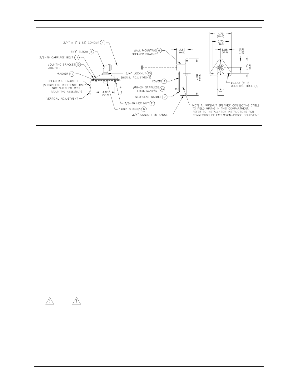
Figure 1. Speaker Mounting Details
Installation
Refer to Figure 1 for the location of the items with ID numbers.
1. Secure the wall mounting bracket (ID# 9) to the wall. Mounting hardware is not included.
2. Thread the cable bushing (ID# 6) to the mounting bracket adapter (ID# 10). Do not tighten the cable
bushing nut.
3. Thread the locknut (ID# 15) onto the ¾-inch male portion of the elbow (ID# 5).
4. Secure the speaker to the mounting bracket adapter (ID# 10) via the U-bracket supplied with the
speaker and the carriage bolts (ID# 14), nuts (ID# 11), and washers (ID# 12) supplied with the kit.
5. Thread the ¾-inch male end of the elbow (ID# 5) into the mounting bracket adapter (ID #10).
6. Thread the one end of the conduit pipe (ID# 4) into the elbow and the other end into the wall
mounting speaker bracket (ID# 9).
7. Feed the SO cord through the cable bushing and down the pipe assembly to the oval opening of the
wall mounting bracket for connection to the speaker/amplifier.
(Note: For speaker driver installation, refer to the publication supplied with the equipment.)
8. Tighten the cable bushing nut. See Note 1 in Figure 1.
NOTE
When using any explosion-proof (Div. 1) speaker or driver unit, the speaker
mounting assembly may be used only to support and orient the speaker. Explosion-proof
fittings must be used for electrical connections.
9. Secure the gasket (ID# 7) and the cover (ID# 3) using the screws provided (ID# 13).