GAI-Tronics 12599-001 Hot Standby Amplifier Module User Manual
Page 3
Pub. 42004-375A
Model 12599-001 Hot Standby Amplifier Module
Page: 3 of 11
\\s_eng\gtcproddocs\standard ioms - current release\42004 instr. manuals\42004-375a.doc
09/05
TB22
– is where the standby amplifier input connects if using a single channel amplifier. If using a dual-
channel amplifier, connect the channel 1 input to these terminals. See Note 1 and Figure 5 and Figure 6.
TB23
– is for busing the standby amplifier input to another (cascaded) module when using a single
channel amplifier. However, if a dual-channel amplifier is used with the module, the channel 2 input of
the standby amplifier should connect to these terminals. See Note 2 and Figure 5 and Figure 6.
TB24 – is where the standby amplifier output connects if using a single channel amplifier. If using a
dual-channel amplifier connect the channel 1 output to these terminals. See Note 2 and Figure 5 and
Figure 6.
TB25 – is for busing the standby amplifier input to another (cascaded) module when using a single
channel amplifier. However, if a dual channel amplifier is used with the module, then the channel 2
output of the standby amplifier should connect to these terminals. See Note 3 and Figure 5 and Figure 6.
TB26 – is the B
RD
C
NTL
(Board Control) I
N
(input) and O
UT
(output), which is used if/when cascading
multiple modules. In a cascade arrangement, no connection is made at the IN terminal at the first module.
For the second module in the cascade, connect the OUT terminal of the first module to IN terminal of the
second module, and continue this wiring scheme across subsequent modules in the cascade. See Note 4
below and refer to Figure 5 and Figure 6.
N
OTES
:
1. A jumper must be installed across the all unused OUT and RET input terminals at TB3 to prevent
false activation of unused circuits.
2. To use both inputs of a dual-channel standby amplifier across multiple (cascaded) modules, wire
TB22 and TB23 in parallel (respectively) across all modules.
3. To use both outputs of a dual-channel standby amplifier across multiple (cascaded) modules, wire
TB24 and TB25 in parallel (respectively) across all modules.
4. Most central amplifier system applications usually employ or specify a ratio of one standby amplifier
for every five or six primary amplifiers to minimize the risk of lost coverage. Be sure to check the
specified system requirements for the ratio of standby (backup) amplifiers to primary amplifiers.
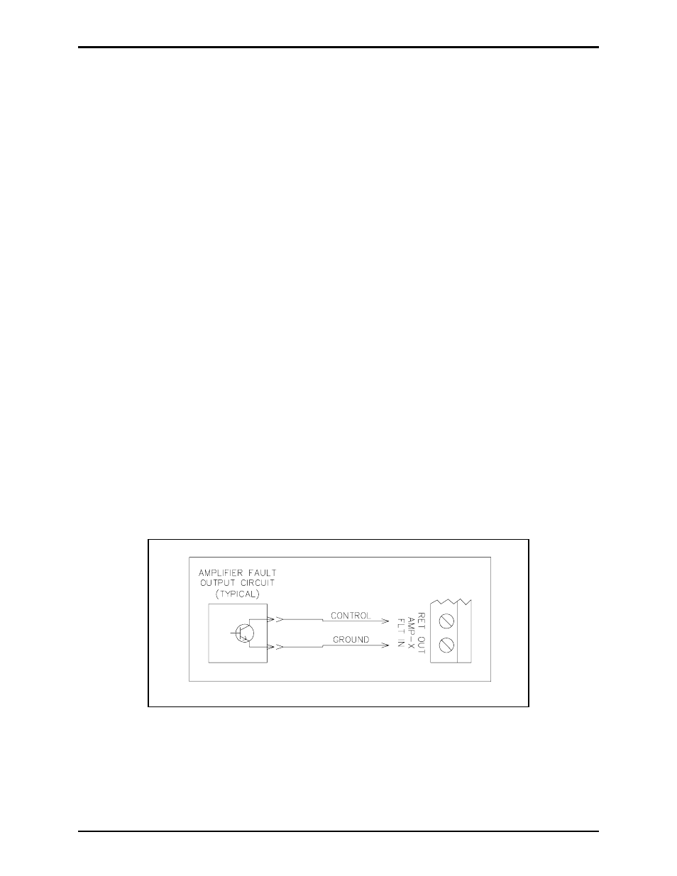
Figure 2. Typical fault input connection