Wiring – GAI-Tronics 530-001 L.E.D. Strobe with Constant-on Feature User Manual
Page 2
Pub. 42004-395I
Model 530-001 LED Strobe with Constant-On Feature
Page 2 of 3
f:\standard ioms - current release\42004 instr. manuals\42004-395i.doc
03/15
Wiring
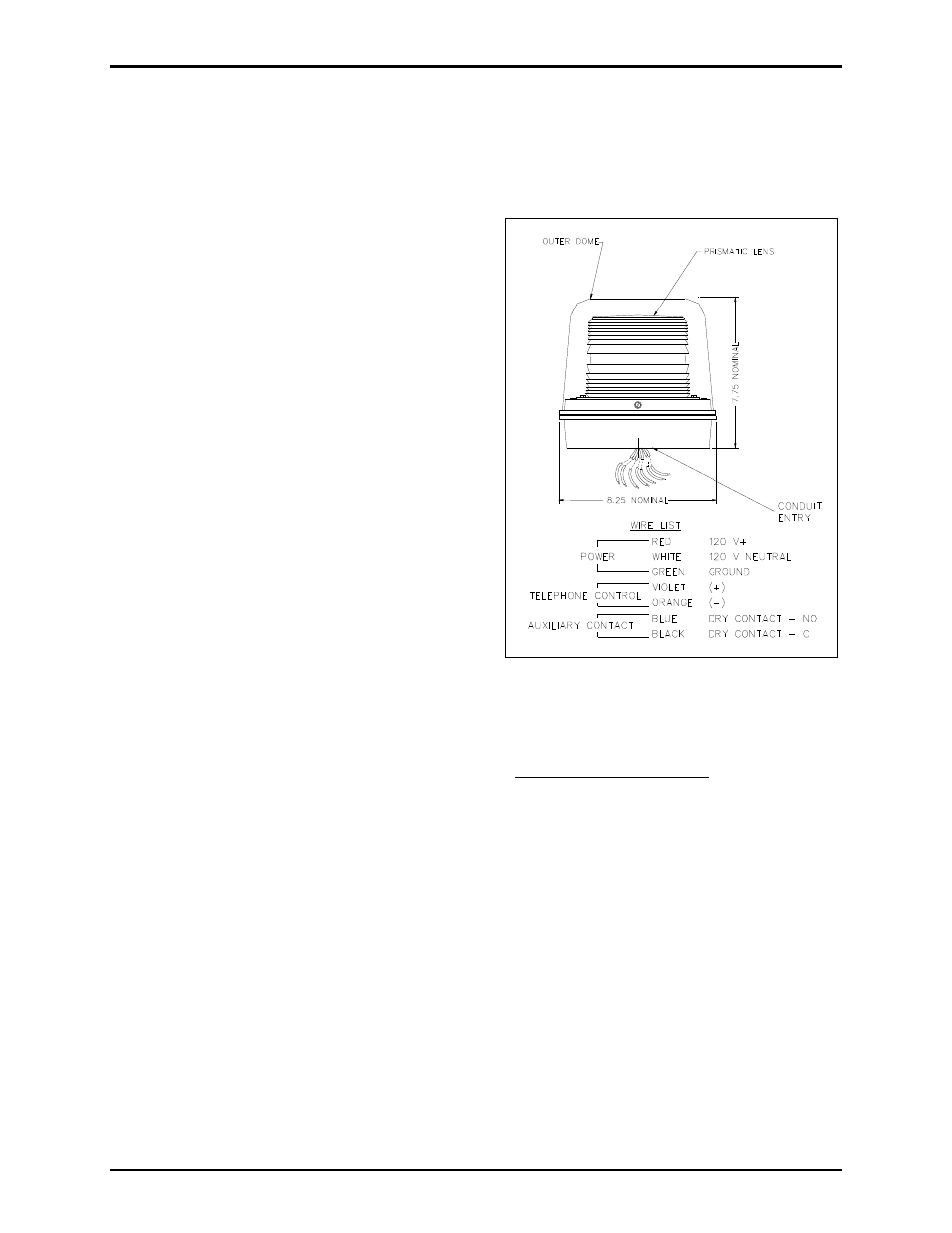
The Model 530-001 LED Strobe is equipped with seven 15-foot conductor leads. Refer to Figure 1. The
red (120 V ac line) and white (120 V ac neutral) leads are connected to the 120 V ac power source. The
green lead is the earth ground wire.
The violet (+) and orange (–) leads are connected to
the emergency telephone to signal the strobe to flash.
The blue and black leads are provided to activate
auxiliary equipment.
1. Connect the red (line) lead to the local power
source.
2. Connect the white (neutral) lead to the local power
source.
3. Connect the green lead to a ground connection.
4. Open the front cover of the emergency telephone
to expose the printed circuit board assembly
(PCBA) and locate the terminal block labeled TB-
2 (OUT1).
5. Bring the violet (+) and orange (–) leads through
the entry hole used for the telephone line.
6. Connect the violet (+) lead to terminal 1 and the
orange (–) lead to terminal 2
on TB2.
7. Replace the front cover on the emergency
telephone and test the unit by pressing the
E
MERGENCY
button. The strobe is only activated
by pressing the E
MERGENCY
button, not the C
ALL
button (if so equipped).
N
OTE
: The LED strobe provides a blue and black wire to activate auxiliary equipment such as signaling
devices or camera call-up controls. These wires provide a dry contact closure rated for 2 amps @
240 V ac, or 2 amps @ 30 V dc, for the duration of the emergency telephone/strobe activation.
Figure 1. Model 530-001 LED Strobe Outline