GAI-Tronics ICS Page/Party Flush-mount Subset User Manual
Ics page/party, Flush-mount subset quick installation guide
Pub. 42004-427BQG
GAI-Tronics Corporation 400 E. Wyomissing Ave. Mohnton, PA 19540 USA
610-777-1374
800-492-1212 Fax: 610-796-5954
V
ISIT WWW
.
GAI
-
TRONICS
.
COM FOR PRODUCT LITERATURE AND MANUALS
G A I - T R O N I C S ® C O R P O R A T I O N
A H U B B E L L C O M P A N Y
ICS Page/Party
®
Flush-Mount Subset Quick Installation Guide
Important Safety Instructions
1. Read, follow, and retain instructions – All safety and operating instructions should be read and followed before operating the unit.
Retain instructions for future reference.
2. Heed warnings – Adhere to all warnings on the unit and in the operating instructions.
3. Attachments – Attachments not recommended by the product manufacturer should not be used, as they may cause hazards.
4. Servicing – Do not attempt to service this unit by yourself. Opening or removing covers may expose you to dangerous voltage or
other hazards. Refer all servicing to qualified service personnel.
5. DB25 connection – The supplied DB25 interconnect cable is designed to be plugged into an ICS Page/Party
®
remote amplifier
only.
General Information and Available Options
This
guide covers the installation of the ICS Page/Party
®
Flush-Mount Subset, which is
designed for indoor flush-mounting into a wall or console. It features one-way page
announcements over system speakers, full-duplex party line communication, and a durable,
highly visible orange powder coat finish. Figure 1 shows the multi-party remote subset.
The flush-mount subset is available with the following options:
Single or multi-party system option
PVC or Hytrel
®
handset cords in 6-, 15-, or 25-foot lengths
Conformal coating for PCBA
Refer to Pub. 42004-427 at the “Manuals & Specs” link at
www.gai-tronics.com
for
detailed explanations of the available options, system information, and warranty.
Mounting and Connection
WARNING
Do not install this equipment in hazardous areas. Such installations
may cause a safety hazard and consequent injury or property damage.
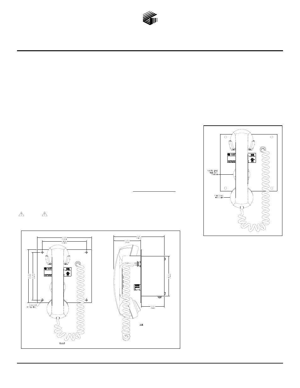
1. Refer to Figure 2 for the subset mounting
hole locations and overall sizes. Refer to
Figure 3 for cutout dimensional
requirements.
2. Plug the interconnect cable into the remote
subset. Feed the opposite end of the cable
into the mounting cutout to the remote
amplifier location.
3. Secure the subset to the mounting surface
using four #10-32 screws and the mounting
holes. Refer to Figure 4 for a typical
installation.
4. Plug the subset interconnect cable into the
remote amplifier.
Figure 1. ICS Multi-Party
Flush-Mount Subset
Figure 2. ICS Multi-Party Flush-Mount Subset Outline