Operation, Functional operation, Maintenance – GAI-Tronics 12598-004 Redundant 48 V DC Module User Manual
Page 3: Troubleshooting
Pub. 42004-468A
Model 12598-004 Redundant 48 V DC Module
Page: 3 of 4
f:\standard ioms - current release\42004 instr. manuals\42004-468a.doc
10/12
Operation
The Model 12598-004 Redundant 48 V DC Module automatically switches to the backup power supply in
the event the primary power supply is lost. After successful installation and testing, it requires no
operator intervention.
Functional Operation
The Model 12598-004 operates with two 48 V dc power supplies. When 48 V dc power is applied to the
PS1
IN and PS2
IN terminals of the module, relays K1 and K2 become active. Output voltage at the DC
OUT terminals will be approximately 47.4 V to 47.1 V dc, which is due to a voltage drop of approx. 0.6
V to 0.9 V depending on the load current through CR1 and CR2. Thus, as load current increases through
the diodes, the voltage drop across each diode increases toward the maximum value of 0.9 V.
Also, since CR1 or CR2 have a slightly different voltage drops (or turn-on thresholds), either of the
connected power supplies (at PS1
IN or PS2
IN) may initially supply power to load.
Maintenance
The Model 12598-004 Module does not contain any user serviceable parts. Do not attempt to make any
repairs to the module. If the module requires service, contact your Regional Service Center for a return
authorization number (RA#). The module should be shipped prepaid to GAI-Tronics with a return
authorization number and a purchase order number. If the module is under warranty, repairs or a
replacement will be made in accordance with GAI-Tronics’ warranty policy. Please include a written
explanation of all defects to assist our technicians in their troubleshooting efforts.
Call 800-492-1212 inside the USA or 610-777-1374 outside the USA for help identifying the Regional
Service Center closest to you.
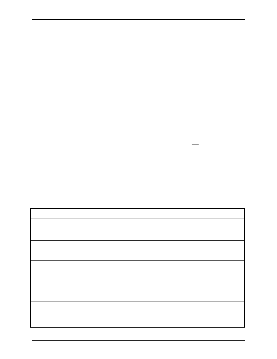
Troubleshooting
Problem Solution
Module is damaged.
Do not attempt to repair the module.
Contact GAI-Tronics service for repair or replacement of the
module in accordance with the information provided on this page.
Voltage is applied to both inputs,
but voltage is not present at the
output terminals.
Verify plug-in connectors at JTB1, JTB2 and JTB3 are properly
inserted.
All connections and connectors are
properly made, but still no output
voltage.
Verify wiring at each connector has proper polarity.
Relay status contact markings are
incorrect when module is not
powered.
The relay status contact markings are based on the module being
actively powered (i.e., in an energized state).
After performing all wiring checks,
trouble-shooting, etc. as described
in this section, the module still does
not function properly.
Contact GAI-Tronics service for repair or replacement of the
module in accordance with the information provided on this page.
- XTA0003A Radio Cable 12564-002 Party Line Knob Kit (EuroPage) XTI0001A-G3 Radio Cable 10959-207 and 10959-208 Rack-mount Audio Messenger Interface 10959-201 and 10959-203 Wall-mount Audio Messenger Interface 10959-903 Wall-Mount Audio Messenger Interface (AMI) XGM003A Gooseneck Microphone Kit 12515-007, 12515-008, 12515-009 Pressbar Handset with Hytrel Cord Replacement Kit