Troubleshooting, Specifications – GAI-Tronics 12594-101 Redundant AZI Switching Module User Manual
Page 5
Pub. 42004-475A
Model 12594-101 Redundant AZI Switching Module
Page 5 of 5
f:\standard ioms - current release\42004 instr. manuals\42004-475a.doc
04/13
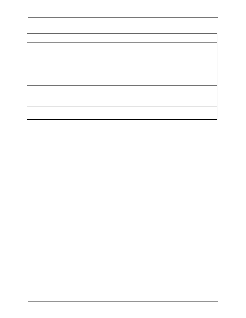
Troubleshooting
Problem Solution
No audio from output terminals
Verify Cat5E cables at J1, J2, J3 and J4 on the module are
properly connected to AZI cards at designated card racks.
Verify amplifiers are connected to the correct outputs along
with proper polarity at TB4.
Verify primary and secondary MCU cards contain correct
software configurations to output audio at designated AZI
amplifier outputs.
Module LEDs do not illuminate
and relays do not switch when
input control is provided.
Verify 12 V dc power is applied to the module.
Verify 12 V dc (−) is being switched to the C
ONTROL
input
at TB2.
Module still does not function after
all checks described in this section.
Contact GAI-Tronics service for repair or replacement of the
module in accordance with the information provided on this page.
Specifications
Electrical
Power requirements ................................................................... 10–14 V dc (12 V dc @ 91.5 mA nominal)
Number of control inputs ......................................................................................................................... One
Number of fault outputs ........................................................................................................................... One
Fault output type .......................................................................................................... Form “C” dry contact
Fault output contact rating .................................................................................... 1 A maximum @ 30 V dc
Connections
RJ45 jacks ............................................................................................................................................... Four
Modular (plug-in) terminal blocks ............................................................................................................ Six
Minimum terminal block conductor size .................................................................. No. 28 AWG (0.5 mm
2
)
Maximum terminal block conductor size .................................................................. No. 12 AWG (3.0 mm
2
)
Mechanical
Module dimensions ........................................ 5.50 L
4.00 W 1.44 H inches (139.7 101.6 36.6 mm)
Module weight .................................................................................................................. 0.38 lbs. (0.17 kg)
Environmental
Temperature range (operating/storage) ..................................................... −4
F to 158 F (−20 C to 70 C)
Humidity .......................................................................................... 85% non-condensing relative humidity