Model 239wm-001 stanchion, Analog telephone wiring – GAI-Tronics 239WM-001 Slim Wall-Mount Stanchions User Manual
Page 4
Pub. 42004-476A
Model 239WM-001 & 239WM-002 Slim Wall-Mount Stanchions
Page
4 of 9
e:\standard ioms - current release\42004 instr. manuals\42004-476a.doc
08/14
Model 239WM-001 Stanchion
Analog Telephone Wiring
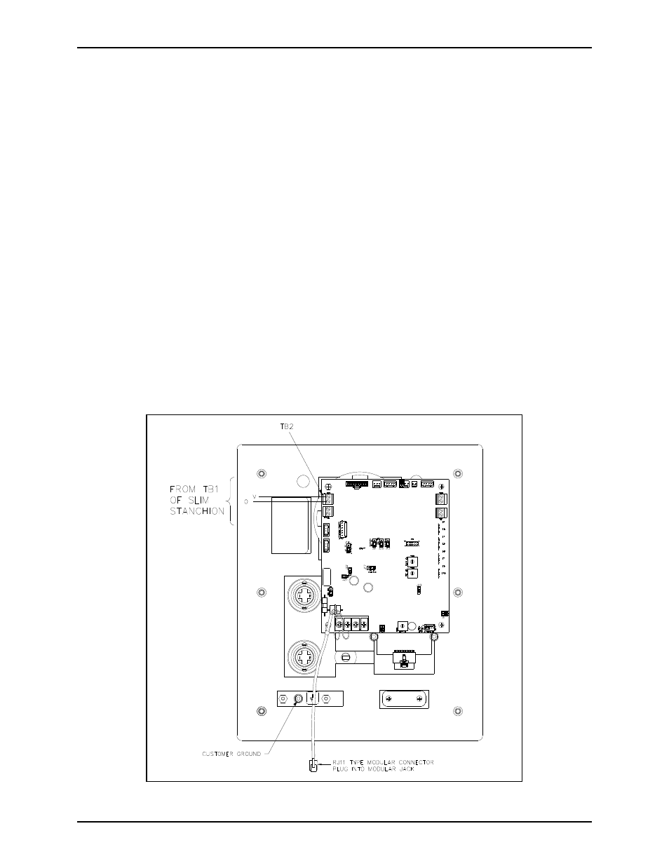
Refer to Figure 2 and Figure 3.
1. Install the telephone line surge suppressor (customer-supplied) on the telephone line, if applicable.
2. Install the surface-mount jack with adhesive pad that is provided with each Flush-Mount Emergency
Telephone by adhering it to the back box at the lower edge.
3. The telephone line must enter the stanchion through one of the holes on the right hand side of the
unit when viewed from the front. Plug the telephone line into the surface-mounted jack assembled in
step 2.
4. The ac power line must enter the stanchion through one of the holes on the left side of the unit when
viewed from the front. Secure the wires to the terminal block as noted on the label.
5. Connect the violet (V) and orange (O) beacon wires inside the stanchion to TB2 on the E-phone
PCBA as shown in Figure 2.
6. Plug the RJ11 modular connector from the telephone into the surface-mount jack installed in step 2.
N
OTE
: Steps 2 and 6 may be skipped and the incoming telephone line can connect directly to TB1 of the
telephone, if desired.
Figure 2.