GAI-Tronics ICS Page/Part Handset/Speaker Amplifier Station User Manual
Ics page/party, Station quick installation guide
Pub. 42004-717L2GQG
GAI-Tronics Corporation 400 E. Wyomissing Ave. Mohnton, PA 19540 USA
610-777-1374
800-492-1212 Fax: 610-796-5954
V
ISIT WWW
.
GAI
-
TRONICS
.
COM FOR PRODUCT LITERATURE AND MANUALS
G A I - T R O N I C S ® C O R P O R A T I O N
A H U B B E L L C O M P A N Y
ICS Page/Party
®
Station Quick Installation Guide
Important Safety Instructions
1. Read, follow, and retain instructions – All safety and operating instructions should be read and followed before operating the unit.
Retain instructions for future reference.
2. Heed warnings – Adhere to all warnings on the unit and in the operating instructions.
3. Attachments – Attachments not recommended by the product manufacturer should not be used, as they may cause hazards.
4. Servicing – Do not attempt to service this unit by yourself. Opening or removing covers may expose you to dangerous voltage or
other hazards. Refer all servicing to qualified service personnel.
5. This permanently connected apparatus must have a UL Listed 15-amp circuit breaker incorporated in the electrical installation of
the building.
General Information and Available Options
This
guide covers the installation of the ICS Page/Party
®
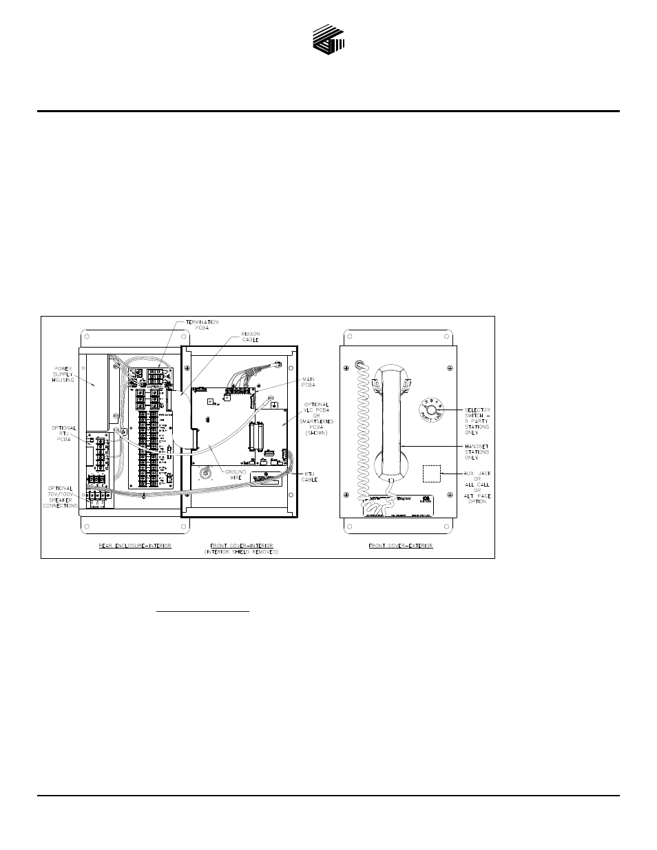
Station. Figure 1 shows configurations with the following options:
Universal ac or 24 V
dc power
Single or multi-party
system, or amplifier
only
All Call
SmartSeries
Alternate page
destination
Emergency party line
Auxiliary jack
VLC
RTU
70V / 100V speaker
output
All ICS Stations are wired in parallel. Good system layout design minimizes the cable required. Refer to Pub. 42004-717L2 at the
“Manuals & Specs” link at
www.gai-tronics.com
for detailed explanations of the available configuration options and adjustments,
system design information, and warranty.
Mounting and Wiring
Mount the enclosure using the four 0.312-inch (8 mm) diameter holes located on the mounting flanges with ¼-inch (M6) hardware.
The standard orientation (shown in Figure 1) locates the power supply housing in the upper left corner. The orientation of the
enclosure can be rotated 180º to allow clear access on the top. The Termination PCBA can then be rotated for correct orientation.
Remove front panel and drill or punch wire entry openings in the rear enclosure. See Figure 2 for suggested locations. There must be
a minimum of ½ inch (12.7 mm) of material between wire entry holes. The recommended entry is via the enclosure bottom to prevent
moisture from dripping onto the terminals. Avoid the top left as it may interfere with the power supply. Basic wiring connections are
shown on Figure 3. Use GAI-Tronics 60029 series multi-party cable or 60038 series single party cable terminated with #6 spade lugs.
Torque the terminal block screws to 8–10 in-lbs (0.90–1.13 n-m) when attaching the spade lugs.
Figure 1. ICS Station with available options (AC Version shown)