GAI-Tronics ICS Page/Party Remote Subset Handset/Speaker Amplifier Station User Manual
Ics class i, div. 2 page/party, Station quick installation guide
Pub. 42004-725L2HQG
GAI-Tronics Corporation 400 E. Wyomissing Ave. Mohnton, PA 19540 USA
610-777-1374
800-492-1212 Fax: 610-796-5954
V
ISIT WWW
.
GAI
-
TRONICS
.
COM FOR PRODUCT LITERATURE AND MANUALS
G A I - T R O N I C S ® C O R P O R A T I O N
A H U B B E L L C O M P A N Y
ICS Class I, Div. 2 Page/Party
®
Station Quick Installation Guide
Important Safety Instructions
This equipment is suitable for use in Class I, Division 2, Groups A, B, C and D, Class II Division 2, Groups F, and G, Class III OR non-hazardous locations only.
Combinations of equipment in your system are subject to investigation by the local Authority Having Jurisdiction at the time of installation.
1. Read, follow, and retain instructions – All safety and operating instructions should be read and followed before operating the unit. Retain instructions for future
reference.
2. Heed warnings – Adhere to all warnings on the unit and in the operating instructions.
3. Attachments – Attachments not recommended by the product manufacturer should not be used, as they may cause hazards. Maximum system cable length is not to
exceed two miles.
4. Servicing – Do not attempt to service this unit by yourself. Opening or removing covers may expose you to dangerous voltage or other hazards. Refer all servicing
to qualified service personnel.
5. This permanently connected apparatus must have a UL Listed 15-amp circuit breaker
incorporated in the electrical installation of the building.
WARNING – EXPLOSION HAZARD – Do not disconnect equipment unless power has been removed or the area is known to be non-hazardous. Averttissement –
Risque d’explosion – avant de déconnector l’equipment, couper le courant ou s’assurer que l’emplacement est désigné non dangereux.
USA and Canada Consult the National Electrical Code (NFPA 70), Canadian Standards Association (CSA 22.1), and local codes for specific requirements regarding
your installation. Class 2 circuit wiring must be performed in accordance with NEC 725.55.
WARNING
In 24 V dc systems: Under NO condition should this equipment be operated from a battery charger without the batteries connected.
In 24 V dc systems, most chargers have an unloaded output of 35 to 45 volts that can quickly damage the equipment designed for nominal 24 volts. The maximum
battery voltage should never exceed the maximum specified input voltage.
General Information and Available Options
This
guide covers the installation of the ICS Page/Party
®
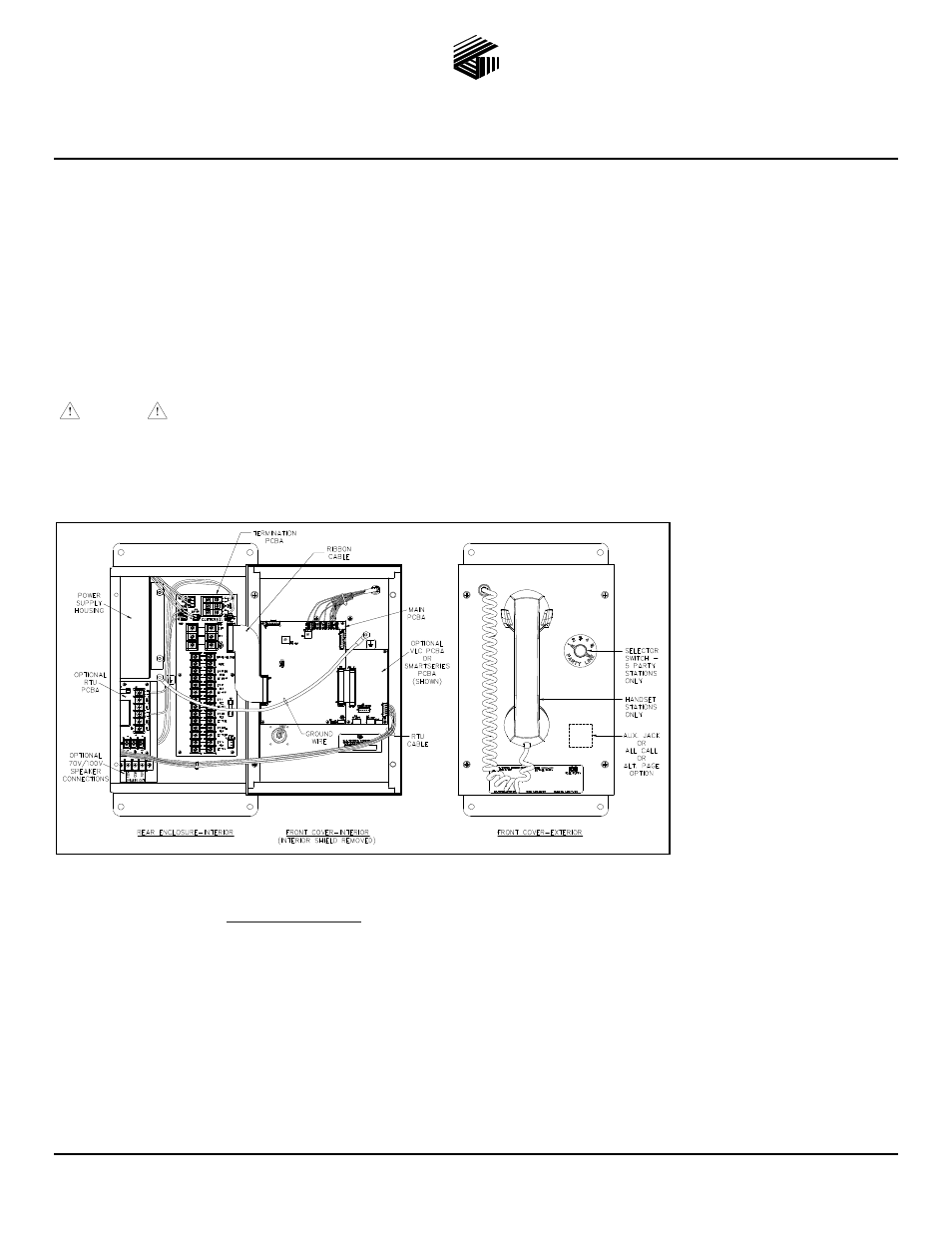
Station. Figure 1 shows configurations with the following options:
Universal ac or 24 V dc
power
Single or multi-party
system, or amplifier only
All Call
SmartSeries
Alternate page destination
Emergency party line
(EPL)
Auxiliary jack
VLC
RTU
70V/100V speaker output
All ICS Stations are wired in parallel. Good system layout design minimizes the cable required. Refer to Pub. 42004-725L2 at the
“Manuals & Specs” link at
www.gai-tronics.com
for detailed explanations of the available configuration options and adjustments,
system design information, and warranty.
Mounting and Wiring
Mount the enclosure using the four 0.312-inch (8 mm) diameter holes located on the mounting flanges with ¼-inch (M6) hardware.
The standard orientation (shown in Figure 1) locates the power supply housing in the upper left corner. The orientation of the
enclosure can be rotated 180º to allow clear access on the top. The Termination PCBA can then be rotated for correct orientation.
Remove front panel and drill or punch wire entry openings in the rear enclosure. See Figure 2 for suggested locations. There must be
a minimum of ½ inch (12.7 mm) of material between wire entry holes. The recommended entry is via the enclosure bottom to prevent
moisture from dripping onto the terminals. Avoid the top left as it may interfere with the power supply. Basic wiring connections are
shown on Figure 3. Use GAI-Tronics 60029 series multi-party cable or 60038 series single party cable terminated with #6 spade lugs.
Torque the terminal block screws to 8–10 in-lbs. (0.90–1.13 n-m) when attaching the spade lugs.
Figure 1. ICS Station with available options (AC Version shown)