Installing the new microphone assembly – GAI-Tronics 12521-001 Microphone Assembly for 281 User Manual
Page 2
Pub. 42003-055B
M
ODEL
12521-001
M
ICROPHONE
A
SSEMBLY
R
EPLACEMENT
K
IT
Page:
2 of 2
\\s_eng\gtcproddocs\standard ioms - current release\42003 kit manuals\42003-055b.doc
06/96
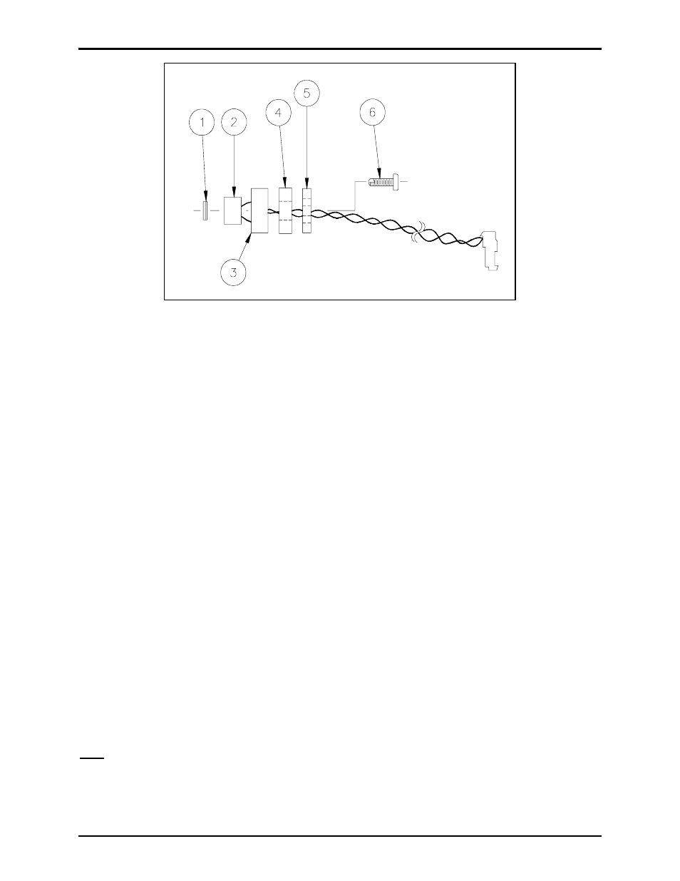
Figure 1. Microphone Assembly
Installing the New Microphone Assembly
Refer to Figure 1.
1. Remove the backing from the gasket assembly (Item 1), and attach it to the front of the microphone
(Item 2).
2. Lay the gasket/microphone assembly in place on the rear of the front panel.
3. Feed the microphone leads through the microphone gasket (Item 3), microphone/gasket bracket
(Item 4), and microphone mounting bracket (Item 5).
4. Insert and tighten the 2 new screws (Item 6).
5. Replace the door by aligning the interior hinge plugs with the rear enclosure and pushing firmly
straight back.
6. Reattach the microphone assembly connector to the PCBA at J5.
7. Reattach the speaker assembly connector to the PCBA at J6.
8. Reattach the push-button connector to the PCBA at J4.
9. Use the new tie wrap to tie the wires together. Make sure the push-button wire is positioned between
the speaker and microphone wires; this will eliminate feedback between the speaker and microphone
wires.
10. Swing the front panel closed, tighten the tamper-resistant screws, and make a test call from the unit.
Note: Installation of a new microphone may require the volume level to be readjusted. In this case, see
the unit’s original installation manual for adjustment instructions.