GAI-Tronics 12512-002 Hookswitch Assembly for 226, 227, 228 User Manual
Page 3
Pub. 42003-092B
M
ODEL
12512-002
H
OOKSWITCH
A
SSEMBLY
R
EPLACEMENT
K
IT
Page
3 of 5
f:\standard ioms - current release\42003 kit manuals\42003-092b.doc
02/13
14. Thread the leads of the reed switch through the center top hole. See Figure 2.
15. Attach the hookswitch mounting block with the single screw. See Figure 2.
16. Tighten all screws to compress the gasket.
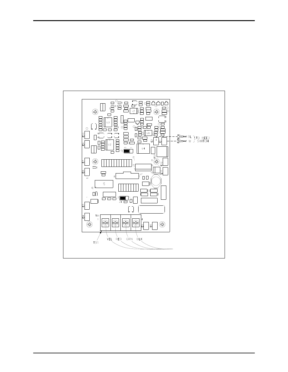
17. Plug spades on the blue and white wires into the appropriate E-clips on the PCBA. For models with
the suffixes -001, -005, and -700, see Figure 3, Figure 5 and Figure 6, respectively. For models with
the suffix -003, clip off the spade lugs and strip the wire ¼ inch and install the leads into terminal
block TB1 on the PCBA. See Figure 4.
Figure 3. Models with -001 suffix
18. Bundle the wires as before with the cable tie included in this kit.
19. For models with the suffix -001, reconnect wires to TB1 as shown in Figure 3.
For models with the suffixes -003, and -005, reconnect the red (Ring) and green (Tip) wires to TB1.
For models with the suffix -700, reconnect the power cord to P11 on the PCBA.
20. Replace the front panel and secure using the screws retained from step 1.
21. Test the on-hook/off-hook function to confirm proper installation.