GAI-Tronics 12526-001 Kit for 13340 Stainless Steel Bracket User Manual
Page 2
Pub. 42003-098C
M
ODEL
12526-001
M
OUNTING
B
RACKET
R
EPLACEMENT
K
IT
Page:
2 of 4
\\s_eng\gtcproddocs\standard ioms - current release\42003 kit manuals\42003-098c.doc
10/98
N
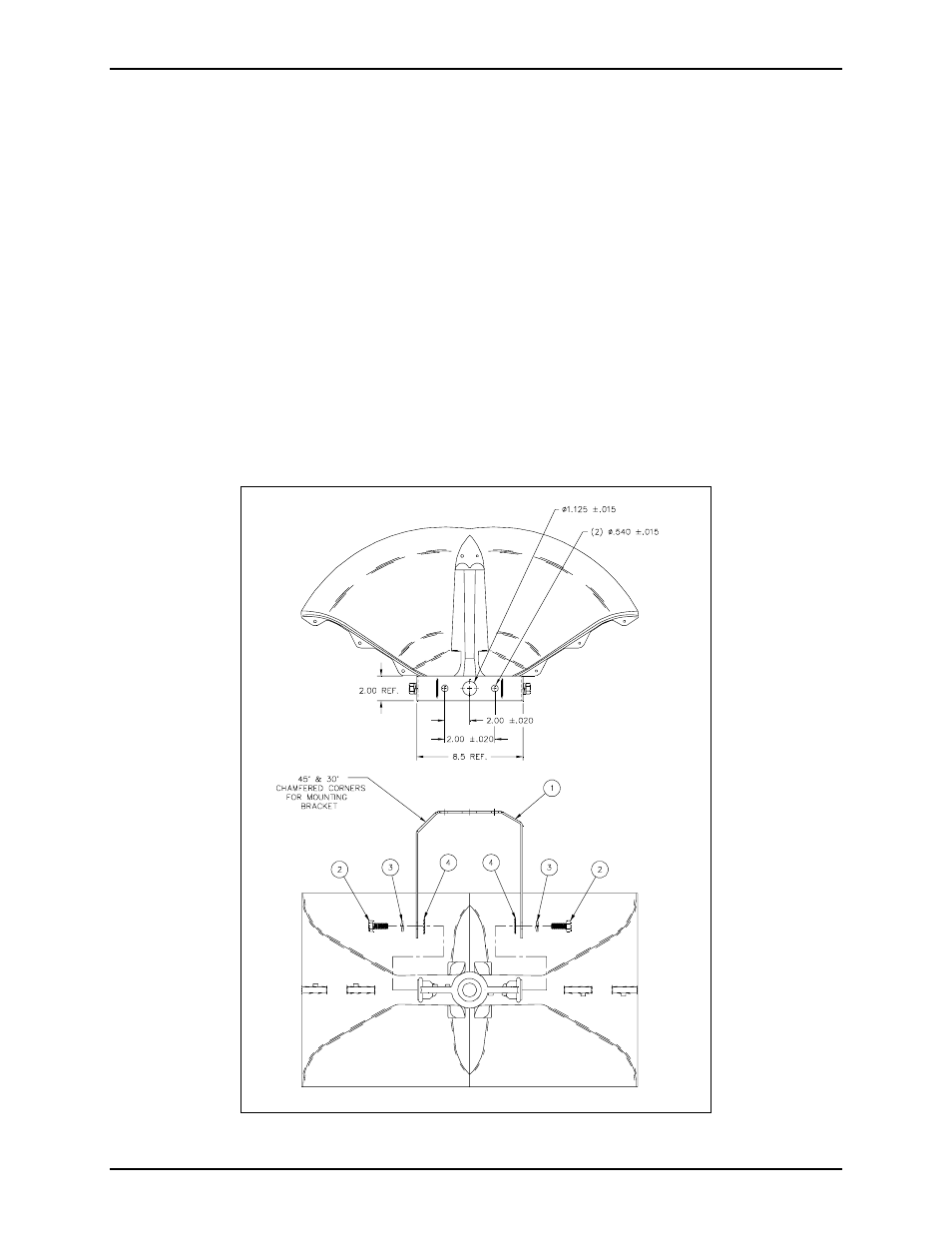
OTE
: The numbers called out in the following instructions refer to the identification numbers in
Figure 1.
1. Disassemble and remove the existing hex bolts, split-ring lock washers, and internal/external tooth lock
washers from each side of the horn. Remove the existing bracket.
(Disassembling the horn body is not required because the square nuts pocketed in the horn will be used
for attaching the new bracket to the horn. New stainless steel hardware is included in this kit to replace
the existing bracket hardware, if needed.)
2. Align the mounting bracket (#1) and the internal/external tooth lock washers (#4) with the side holes of
the speaker mounting ears. [The bracket can be reversed to place the chamfered corner on a particular
side. Chamfered corners can be used as an alternate mounting method (using welding or bolting) to
mount the bracket at a particular angle.]
3. Insert the hex bolts (#2) through the split-ring lock washers (#3), the mounting bracket (#1), and the
internal/external tooth lock washers (#4), and tighten them into the square nuts located inside the
speaker mounting ears.
4. Orient the horn to the desired position, and tighten the ½-inch hex bolts to 180–210 in-lbs. torque.
Figure 1.