GAI-Tronics 12250-001 VLC Kit User Manual
Page 4
Pub. 42003-109E
M
ODEL
12250-001
V
OLUME
L
EVEL
C
ONTROL
R
ECEIVER
A
SSEMBLY
R
EPLACEMENT
K
IT
Page:
4 of 7
\\s_eng\gtcproddocs\standard ioms - current release\42003 kit manuals\42003-109e.doc
10/02
Disassembly
1. Loosen the 4 front panel screws, and remove the amplifier from the enclosure.
2. Loosen the 4 screws on the side, and slide the chassis to remove the front panel. If the unit does not
contain a handset, immediately set the front panel aside.
3. If the unit contains a handset, disconnect the wires at the printed circuit board assembly (PCBA), and
set the front panel aside. Note the wire color and location prior to removal to allow for easier re-
assembly.
Note: Skip Step 4 if the amplifier does not have a chassis-mounted transformer.
4. Place the chassis on the bench with the connector toward you. Disconnect the transformer by removing
the 2 mounting screws. Disconnect the 6-pin Molex connector from the PCBA, and set it aside.
Note: On Model 701-204, 701-205, and 701-304 also disconnect the two 6-pin Molex connectors
from the PCBAs associated with the auxiliary handset jack. Make note of the connector(s) position
when removing them, as the connector(s) will be reinstalled later. Remember to save the parts.
CAUTION
Removal of the PCBA before drilling is advisable.
5. Loosen the 2 screws holding the amphenol connector to the chassis. If the amplifier contains a small
PCBA (Model 69072-001) mounted to the chassis, detach this by removing the 4 screws, and set them
aside. Note the board’s orientation.
6. Using pliers, press the plastic standoffs through the back of the chassis to remove the PCBA. Set the
PCBA aside. Be careful not to break the standoffs when pushing them through.
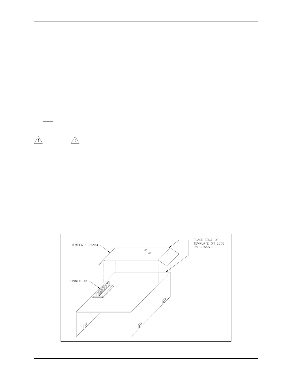
7. Turn the chassis over. With the connector opening at the top of the chassis, place the template along
the right edge of the chassis as shown on the diagram. Refer to Figure 3 below.
8. With the template in place, carefully center punch the holes. Drill two
5
/
32
-inch holes, and deburr the
opposite side.
Figure 3. Template 25354