Installation as a subset extension cord – GAI-Tronics 12587-001 Subset Extension Cable User Manual
Page 3
Pub. 42003-111A
M
ODEL
12587-001
S
UBSET
E
XTENSION
C
ABLE
A
SSEMBLY
R
EPLACEMENT
K
IT
Page
3 of 4
f:\standard ioms - current release\42003 kit manuals\42003-111a.doc
10/12
Installation as a Subset Extension Cord
1. Arrange the cable so that P1 is located at the amplifier enclosure or wall receptacle. After all the
connections are made, P1 will plug into the receptacle at the amplifier enclosure or wall receptacle,
and the blunt end of the cable will be wired to the 24-position receptacle (J1) and will plug into the
subset plug.
2. Cut the cable to the desired length needed to reach from the amplifier enclosure or wall receptacle to
the existing subset cable.
3. From the blunt end of the cable, strip the cable jacket off for 1.75 inches, and the 24-wire lead
jackets for 0.25 inch. Install the cable clamp housing on the cable prior to soldering the leads to the
receptacle J1 terminals.
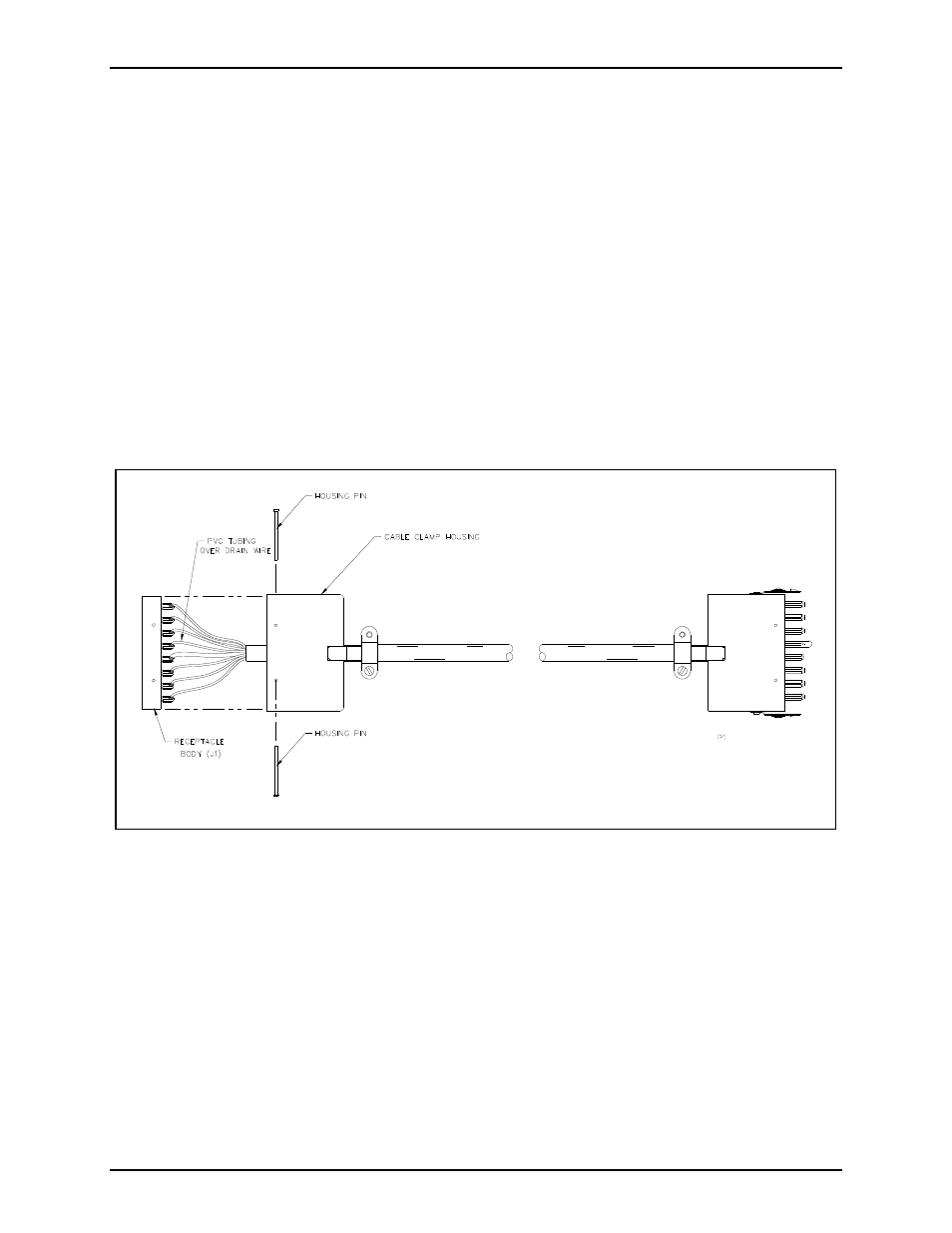
4. The cable contains one shielded pair of wires with a drain wire. Trim the shield until it is even with
the cable jacket. Twist the drain wire, and cover it with the 1.5-inch PVC tubing (supplied) prior to
soldering terminal 14 of receptacle J1.
Figure 2. Installation as a Subset Extension
5. See Figure 4 for proper wire color terminations. Solder all wire leads and the drain wire to
receptacle J1 as indicated in Figure 1. Make sure that there are no wire strands touching any other
terminations.
6. Install the cable clamp housing over the receptacle body, and install the housing pins from opposite
sides of the housing, then tighten the cable clamp screws.
7. Plug P1 into the amplifier enclosure or wall receptacle.