Installation – GAI-Tronics 12607-001 Multi-Party Switch Kits & Harness Assembly User Manual
Page 2
Pub. 42003-117B
M
ULTI
-P
ARTY
S
WITCH AND
H
ARNESS
R
EPLACEMENT
K
IT
Page:
2 of 2
\\s_eng\gtcproddocs\standard ioms - current release\42003 kit manuals\42003-117b.doc
6/98
Installation
Model 12607-001 5-Party Line Switch Kit for Indoor Stations
1. Remove the knob and the old switch. Use a
1/16
-inch (#21) Allen
wrench to loosen the 2 set screws in the selector knob. One screw
is to the right of the party-line indicator; the other screw is in the
end of the knob. After loosening the screws, lift the knob off, and
set it and the screws aside. Save the knob.
2. Write down where all the wires and jumpers are connected.
3. Remove all the wires and jumpers from the old switch.
Note: Keep the wires as long as possible.
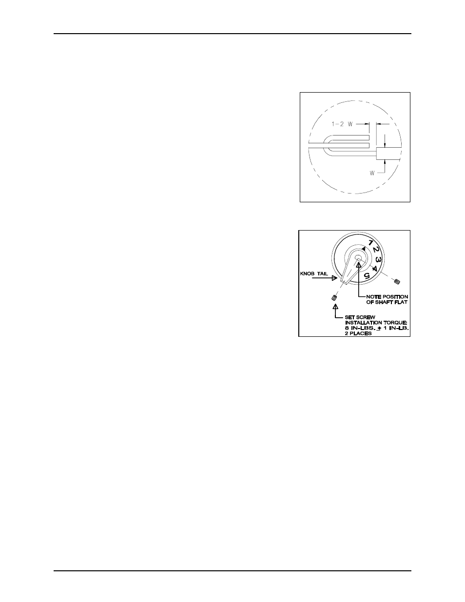
4. J-hook all the connections before soldering on the new switch. This
process will ensure a good mechanical connection. See Figure 1.
Knob Installation
Suggested Tools
•
1/16
-inch (#21) Allen Wrench
• Adjustable Torque Driver
1. Set adjustable torque driver to 8 inch-pounds.
2. Tighten the set screw at the tail end of the switch. Note the position
of the shaft flat with respect to the tail of the knob. See Figure 2.
3. Tighten the remaining set screw.
Figure 1. Proper J-Hook
Figure 2. Knob Installation