GAI-Tronics 12550-102 Receiver Kit for PCBA Electro-Sound User Manual
Page 3
Pub. 42003-149
M
ODEL
12550-102
R
ECEIVER
A
MPLIFIER
R
EPLACEMENT
K
IT
Page:
3 of 3
\\s_eng\gtcproddocs\standard ioms - current release\42003 kit manuals\42003-149.doc
8/95
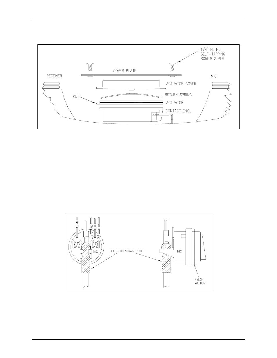
6. Install the page switch contact enclosure, actuator, return spring, actuator cover, and cover plate using
the screws previously removed. See Figure 3.
7. Connect the three black wires from the receiver PCBA, page switch, and coil cord to one terminal of
the microphone and the brown wire from the receiver PCBA to the second terminal of the microphone.
See Figure 4.
8. Carefully insert the tape splice into the microphone cavity, and push the wires toward the page switch.
Install the coil cord strain relief on the microphone bracket as shown in Figure 4. Insert the
microphone into the microphone cavity on the handset.
9. Install the nylon washer on the microphone. See Figure 4.
10. Replace the microphone cap.
Figure 3. Pressbar Page Switch Detail Drawing
Figure 4. Microphone Installation Diagram