GAI-Tronics 12518-101 PCBA Keypad and Seal Kit User Manual
Page 2
Pub. 42003-165
M
ODEL
12518-101
PCBA,
K
EYPAD
,
AND
S
EAL
R
EPLACEMENT
K
IT
Page:
2 of 2
\\s_eng\gtcproddocs\standard ioms - current release\42003 kit manuals\42003-165.doc
9/97
Removing the Existing PCBA and Keypad
1. Loosen the four front cover screws.
2. Pull out the front panel assembly about 6–8 inches. Disconnect the modular telephone cord.
3. Disconnect the handset, hookswitch, ringer, and keypad wires from the printed circuit board assembly
(PCBA).
4. Remove the six screws securing the PCBA.
5. Remove the PCBA, gasket, and the keypad sealing panel. Discard the PCBA and seal.
Installing the New Keypad Seal and PCBA
1. Attach and secure the keypad seal and PCBA onto the front cover using the four #4 - 40
×
7
/
8
-inch
screws.
2. Slide the
1
/
8
-inch spacers on top of the standoffs located at the bottom of the board, and fasten in place
using the two #4 - 40
×
3
/
8
-inch screws provided in this kit.
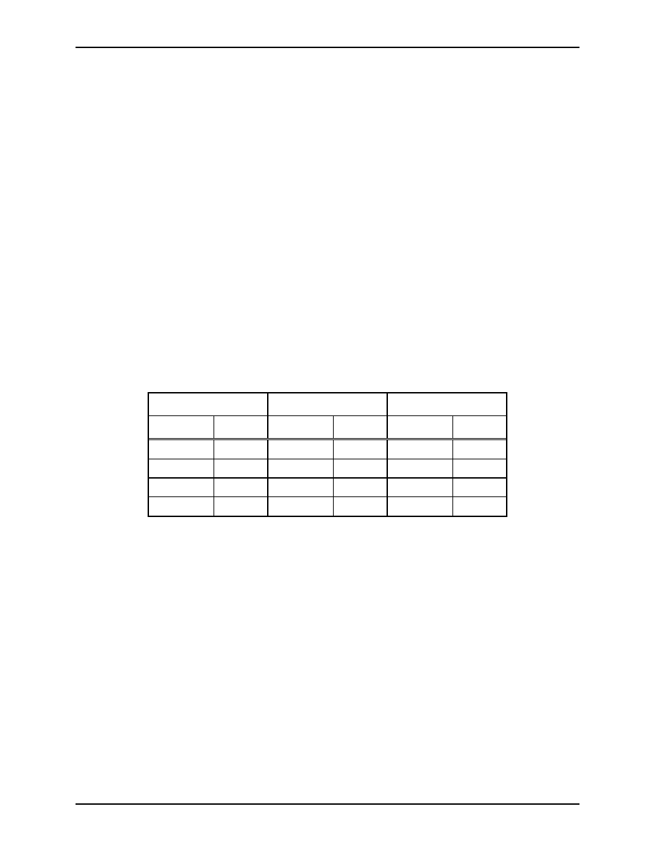
3. Make the following connections to the PCBA terminal strip.
Handset Hookswitch Ringer
Terminal Wire Terminal Wire Terminal Wire
E1 Red
E5 Blue
E7 Black
E2 Green
E6 White
E8 Gray
E3
White
E4
Black
4. Connect the modular telephone cord to the PCBA terminal strip.
5. Replace the front cover assembly onto the rear enclosure. Replace and tighten the four front cover
screws.
6. Check telephone for dial tone.