Installing the new power supply – GAI-Tronics 12560-004 PCBA AC Power Supply Replacement Kit User Manual
Page 2
Pub. 42003-171
M
ODEL
12560-004
P
OWER
S
UPPLY
R
EPLACEMENT
K
IT
Page:
2 of 3
\\s_eng\gtcproddocs\standard ioms - current release\42003 kit manuals\42003-171.doc
2/98
5. Remove the ac connector from the power supply.
6. At the rear of the power supply panel, remove the four power supply mounting screws, and free the
power supply.
Installing the New Power Supply
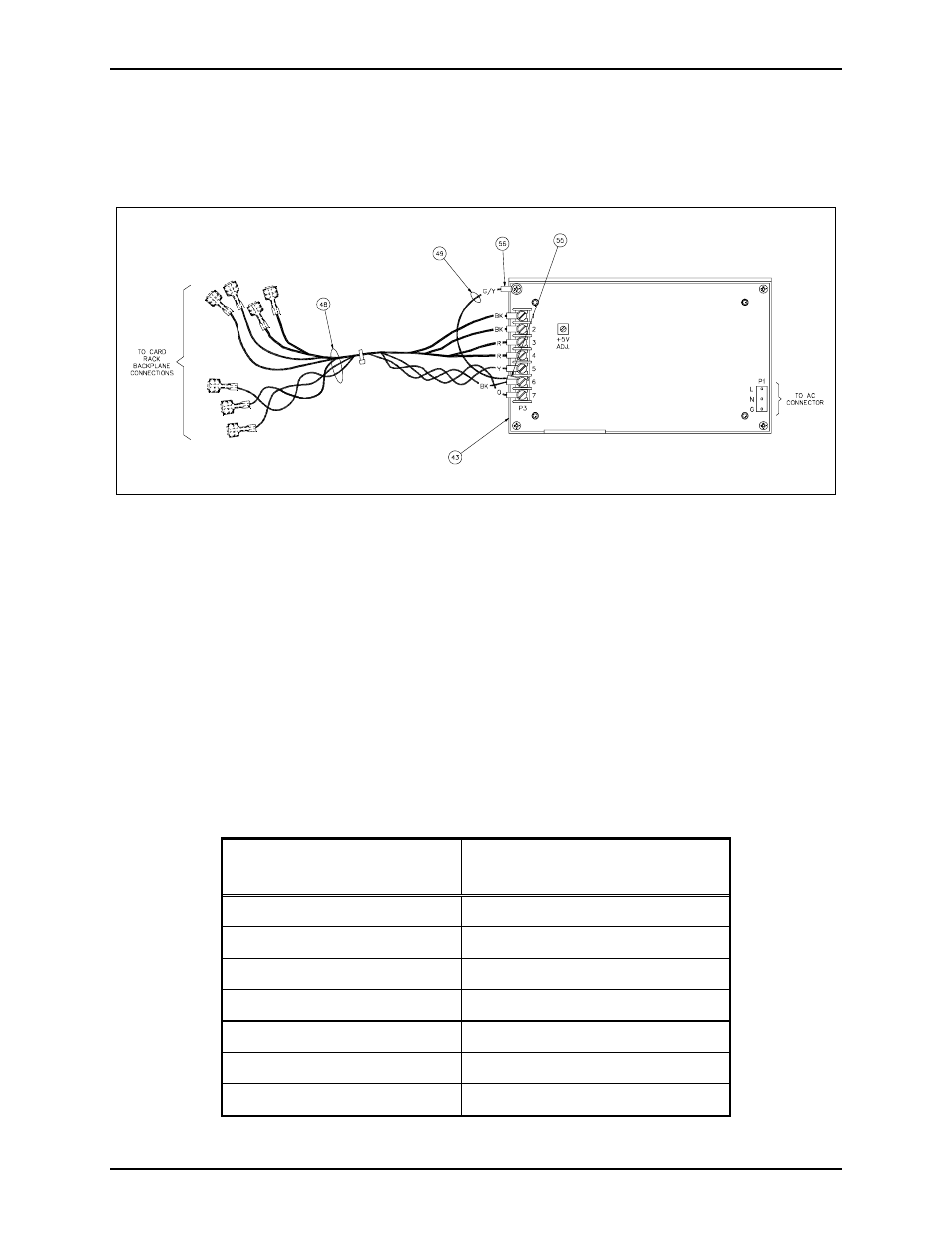
Refer to Figure 1 and Figure 2 for component location and installation details.
1. Attach the replacement power supply to the panel using the four power supply mounting screws.
2. Reattach the ac connector to the power supply and reattach the harness assembly’s FASTON™ lugs to
the backplane PCBA at the appropriate locations. Use firm pressure to insure a tight connector fit.
See Table 1.
Table 1.
Power Supply
Harness Wire Color
TO: Backplane Terminal
No. 14 AWG Red
+5 volts
No. 14 AWG Red
+5 volts
No. 14 AWG Black
GND (D GND)
No. 14 AWG Black
GND (D GND)
No. 18 AWG Black/White
+5 volt standby (A-GND)
No. 18 AWG Orange
+12 volts
No. 18 AWG Yellow
-12 volts
Figure 1.