Installation, Removing the old front panel controls, Installing the new front panel controls – GAI-Tronics 12504-009 Front Panel Control Replacement for EZ Page Intercom User Manual
Page 2
Pub. 42003-177A
M
ODEL
12504-009 EZ
P
AGE
F
RONT
P
ANEL
C
ONTROLS
R
EPLACEMENT
K
IT
Page: 2 of 3
\\s_eng\gtcproddocs\standard ioms - current release\42003 kit manuals\42003-177a.doc
5/99
Installation
WARNING
Disconnect power from the unit before opening or servicing the unit.
Removing the Old Front Panel Controls
1. Disconnect power to the unit.
2. Using the hex allen wrench, loosen the two screws that secure the knob and remove.
3. Using the #2 screwdriver, remove the six front panel screws that secure the front cover to the housing.
4. Slowly pull the front cover assembly from the rear housing—do not stress the attached wires.
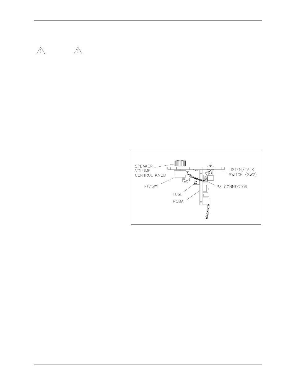
5. Disconnect the connector
(P3) from the internal printed circuit board assembly (PCBA).
Note the orientation of the
potentiometer/switch (R1/SW1) and
the toggle switch (SW2) for
installation of the new controls.
6. Using the 5/8-inch wrench, remove
and discard the sealing nut holding the
toggle switch to the front cover.
7. Using the 1/2-inch wrench, remove
and discard the sealing nut holding the
potentiometer/switch to the front
cover.
N
OTE
: This will allow separation of
the front cover from the PCBA’s
heatsink plate.
8. Discard the wired switch assembly.
Installing the New Front Panel Controls
1. Remove any hardware that might be pre-attached to the new speaker volume/on-off switch; it is not
used in this application.
2. Ensure that the new speaker volume/on-off switch is turned fully counterclockwise to the off position.
Figure 1. Location of Controls