GAI-Tronics 12250-002 Volume Level Control Receiver Assembly (120 V ac) User Manual
Page 4
Pub. 42003-203B
M
ODEL
12250-002
V
OLUME
L
EVEL
C
ONTROL
R
ECEIVER
A
SS
’
Y
(120
V
AC
)
R
EPLACEMENT
K
IT
Page
4 of 7
f:\standard ioms - current release\42003 kit manuals\42003-203b.doc
10/13
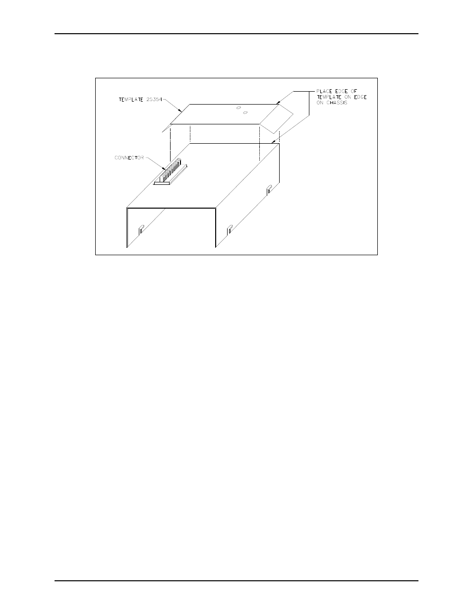
7. Turn the chassis over. With the connector opening at the top of the chassis, place the template along
the right edge of the chassis as shown in Figure 3 below.
Figure 3. Template 25354
8. With the template in place, carefully center punch the holes. Drill two
5
/
32
-inch holes, and de-burr the
opposite side.
9. Orient the PCBA with the connector at the top.
N
OTE
: Step 10 is applicable for models that have R14 installed in the off-hook detection circuitry.
Refer to applicable models and associated boards in Figure 4’s Wiring Details “4A”, “4B”, and “4C”
on page 6 for listing.
10. Replace R14 by de-soldering and removing the old resistor (10,000-ohm, ¼-watt, 5%
[brown-black-orange-gold]). Insert the 4,700-ohm, ¼-watt, 5% (yellow-violet-red-gold] resistor
provided in this kit into the PCBA, and re-solder it. Trim the resistor leads to avoid possible shorts
after re-assembly. See Figure 4.
11. De-solder and remove the W-3 jumper (0-ohm resistor) between E25 and E26. See applicable model
in Figure 4 on page 6.
12. Remove solder from the following pads with a solder remover tool. If a solder remover tool is not
available, use a solder wick to remove the solder: E23, E24, E25, E26, E28, and E31.
N
OTE
: P1 connections do not require removing the solder. Heat the pin with the soldering iron, and
push the wire in.