GAI-Tronics 12562-106 S.M.A.R.T. Auxiliary Powered Emergency Telephone PCBA Replacement Kit User Manual
Page 3
Pub. 42003-211A
M
ODEL
12562-106
S.M.A.R.T.
E
MERGENCY
T
ELEPHONE
PCBA
R
EPLACEMENT
K
IT
Page:
3 of 4
\\s_eng\gtcproddocs\standard ioms - current release\42003 kit manuals\42003-211a.doc
05/05
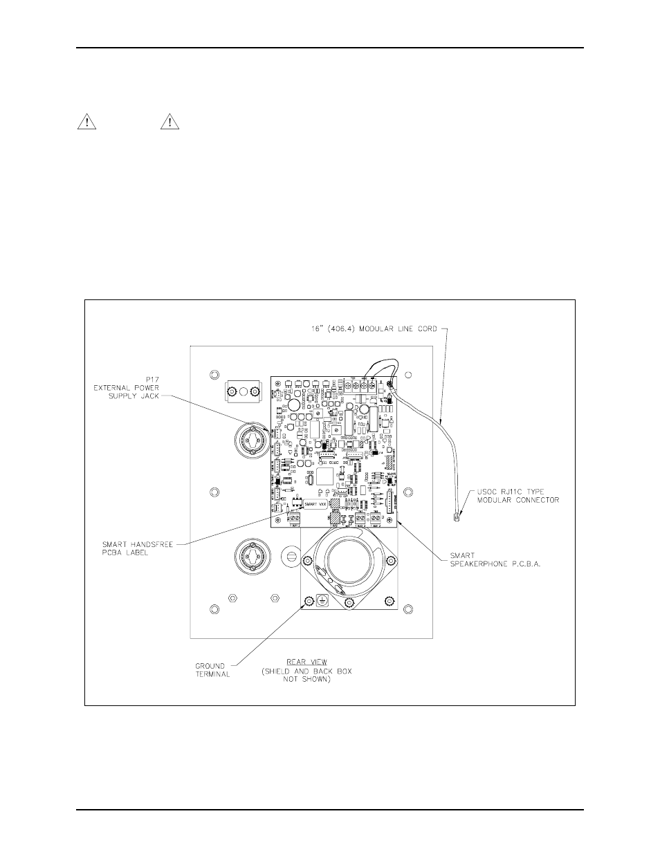
Models 297-103 and 298-103
Removing the Old PCBA
CAUTION
Disconnect the phone line.
1. Use the Model 233-001 Tamper-Resistant Screwdriver to loosen the six front panel screws.
2. Disconnect the microphone, speaker, switches, LED indicator, external power supply connector, and
keypad cables (Model 298-103 only) from the PCBA. Record the location of each connection for later
reconnection.
3. Disconnect the red and green wires from the telephone line connection on the PCBA. Save the modular
cord.
4. Unscrew the four screws securing the PCBA. Save the screws, and discard the PCBA.
Figure 2. Models 297-103 and 298-103 - Printed Circuit Board Detail