Opening the station, Installing the rtu pcba – GAI-Tronics 12820-001 Hazardous Area ICS RTU Upgrade Kit User Manual
Page 2
Pub. 42003-234C
M
ODEL
12820-001
H
AZARDOUS
A
REA
ICS
RTU
U
PGRADE
K
IT
Page
2 of 3
f:\standard ioms - current release\42003 kit manuals\42003-234c.doc
09/12
Opening the Station
Remove all cover bolts from the enclosure. Swing the front door open to access the internal PCBAs. See
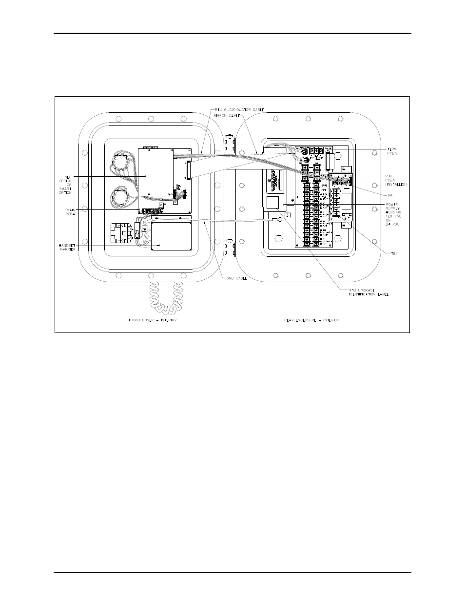
Figure 1.
Figure 1. ICS Hazardous Area Station – Interior View
Installing the RTU PCBA
1. Install the four standoffs (provided) and washers onto the brackets.
2. Align the RTU PCBA with the four standoffs so that TB7 is oriented toward the Termination PCBA.
See Figure 1.
3. Secure the RTU PCBA using the four 4-40 screws provided.
4. Attach the RTU bracket to the rear mounting panel using the two 6-32 screws provided.
5. Install the provided 6-conductor harness from P5 of the SmartSeries or VLC PCBA to P5 of the RTU
PCBA.
6. Place RTU upgrade identification label on power supply bracket as shown on Figure 1.