GAI-Tronics 12520-009 and 12520-010 Round Push-Button Assembly Replacement Kit for 300 Series Telephones User Manual
Page 2
Pub. 42003-238B
M
ODELS
12520-009
AND
12520-010
R
OUND
P
USH
-B
UTTON
A
SSEMBLY
R
EPLACEMENT
K
IT
Page:
2 of 4
f:\standard ioms - current release\42003 kit manuals\42003-238b.doc
05/13
3. Disconnect the telephone line
cord, and strobe wire, if
applicable.
4. Place the front cover assembly
face down on a flat surface.
5. Use the wire cutters to snip the tie
wrap that is securing the push-
button assembly cable to the other
wires.
6. Unplug the push-button assembly
cable connector from the PCBA.
Be sure to note the location of the
connection for re-assembly.
7. Remove #4-40 screws securing
PCBA to standoffs using #1
Phillips screwdriver. Pull the
PCBA away.
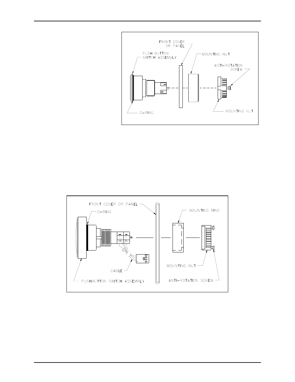
8. Using the appropriate screwdriver, loosen the anti-rotation screws on the mounting nut. See Figure 1
and Figure 2.
9. Remove and discard the mounting nut, the mounting ring, and the push-button assembly.
Figure 2. Push-Button Switch Assembly, Exploded View
(Red Emergency Push Button shown.)
Figure 1. Push-Button Switch Assembly, Exploded View
(Black Emergency Push Button shown.)