Installing the new piezo switch assembly – GAI-Tronics 12520-011 and 12520-012 Piezo Switch Assembly Replacement Kit for 300 Series Telephones User Manual
Page 2
Pub. 42003-239B
M
ODELS
12520-011
AND
12520-012
P
IEZO
S
WITCH
A
SSEMBLY
R
EPLACEMENT
K
IT
Page
2 of 3
f:\standard ioms - current release\42003 kit manuals\42003-239b.doc
08/12
4. Place the front cover assembly
face down on a flat surface.
5. Use the wire cutters to snip the tie
wrap that is securing the push-
button assembly cable to the other
wires.
6. Unplug the piezo switch cable
assembly connector from the
PCBA. Be sure to note the
location of the connection for re-
assembly.
7. Remove #4-40 screws securing
PCBA to standoffs using #1
Phillips screwdriver. Pull PCBA
away.
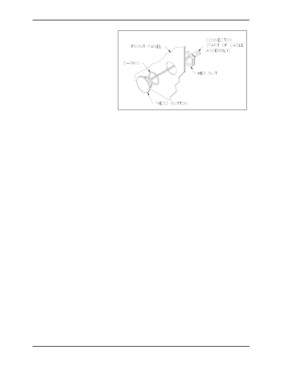
8. Using the 1-1/4 inch box wrench, loosen the hex nut. See Figure 1 for location.
9. Remove and discard the hex nut and piezo switch assembly. Remove any residual gasket material
from the front cover.
Installing the New Piezo Switch Assembly
1. Slide the O-ring over the piezo switch threads to the undercut location.
2. From the front side of the panel, push the new push-button assembly through the hole. See Figure 1.
3. Secure the piezo switch assembly to the front cover using the hex nut. See Figure 1.
4. Use the enclosed tie wrap to secure the push-button assembly cable to the other wires, and attach to
the anchor.
5. Replace the #4-40 screws that secure the PCBA to the standoffs.
6. Plug the push-button assembly cable into the PCBA at the proper location noted earlier.
7. Reconnect the telephone line cord, and strobe wires, if applicable.
8. Align the front cover with the rear enclosure, and use the Model 233-001 Security Screwdriver to
secure four front cover screws (previously saved).
Figure 1. Piezo Push-Button Switch Assembly, Exploded View