Installation – GAI-Tronics 12549-001 and 12549-002 Fiber Module Modification Kit for LE200 Series User Manual
Page 2
Pub. 42003-242A
M
ODEL
12549-001
AND
12549-002
LE200
F
IBER
M
ODULE
M
ODIFICATION
K
ITS
Page:
2 of 4
f:\standard ioms - current release\42003 kit manuals\42003-242a.doc
05/11
Qty. Description
1
Fiber optic chassis
2 Nuts,
#8-32
1
Wire, green/yellow, 18 inches long
1
No. 14 AWG ring lug
1
Spade terminal, #6, No. 14–16 AWG
2
Spade terminals, #6, No. 22–16 AWG
1
Ferrule, Twin 2
× No. 18/20 AWG, red
1
CAT5 cable with ferrules
1
Nylon tie cable, 1.25 inches long
Installation
1. Ensure the power is OFF.
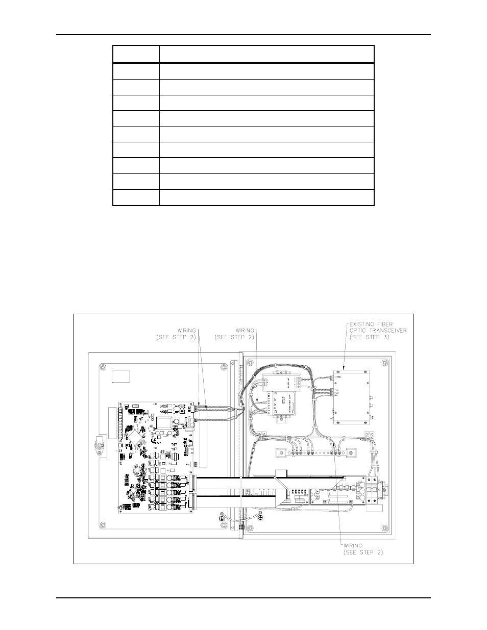
2. Disconnect the power wiring that runs from the Fiber Optic Transceiver and 12 V dc power supply,
and save for later use. Disconnect the data cable that runs from the Fiber Optic Transceiver to P19
on the Line Extender Main PCBA and discard. Remove the ground wire that runs from the Fiber
Optic Transceiver to the grounding bar and discard. Refer to Figure 1.
Figure 1.