Model 276-001 installation – GAI-Tronics 12565-0009, 12565-010 Ring Relay Kits User Manual
Page 4
Pub. 42003-274A
M
ODEL
12565-009
AND
12565-010
R
ING
D
ETECT
K
ITS
Page
4 of 7
f:\standard ioms - current release\42003 kit manuals\42003-274a.docx
01/15
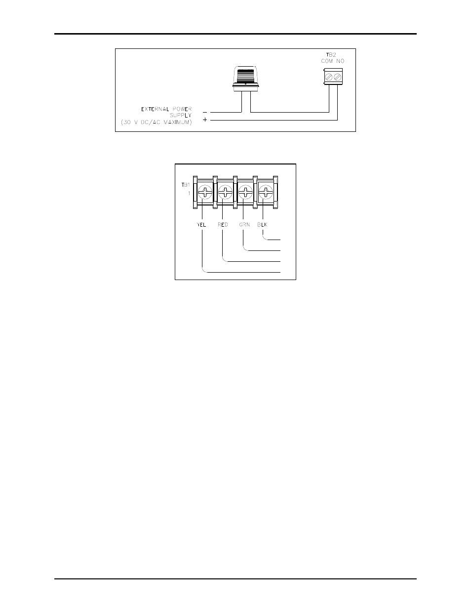
Figure 3. Device Interconnection
Figure 4. TB1 Terminal Block on Industrial Telephone PCBA
Model 276-001 Installation
Using the parts provided in the Model 12565-009 Ring Detect Relay Kit:
1. Remove six 10-32 security screws from front cover of telephone. Pull cover away from the back
box/enclosure. Retain the screws.
2. Disconnect the incoming subscriber telephone line; red (ring) and green (tip) from TB1 on the
Industrial Phone PCBA.
3. Install the two 6-32
1.25-inches F/F standoffs (provided) onto the two weld studs on the back of the
panel. See Figure 5.
4. Align the Ring Relay PCBA with the two standoffs. (Note the PCBA orientation in Figure 1).
5. Secure using two #6-32 screws provided.
6. Connect the incoming subscriber telephone line to TB1 on the Ring Relay PCBA as shown on
Figure 2.
7. Connect the external sounder or beacon to TB2 on the Ring Relay PCBA for activation with an
incoming telephone call. See Figure 2 and Figure 3.
8. Before reattaching the panel assembly, connect the USOC RJ11C modular connector cord (provided)
from the Industrial Phone PCBA shown in Figure 4 to the Ring Relay PCBA shown in Figure 2.