GAI-Tronics XCP0030A Telco Interface Kit User Manual
Page 3
Pub. 43003-014B
Model XCP0030A Telco Interface Kit
Page: 3 of 4
11/02
4. Plug one end of a standard DB50 connector plug into the single 50-pin Telco connector and terminate
the other end to an applicable punch block. Place the connector plug bracket over the 50-pin
connector and secure with two screws. The bracket secures the connector to the Telco interface.
5. Reattach the necessary accessory cables and reconnect the power.
Note: The Supervisor unit input connectors and output connectors can each have a separate Telco
Interface unit attached.
ICP9000 Navigator Series MCU
1. Disconnect the power from the ICP9000 Navigator Series MCU and remove all attached land-line
and accessory cables from the rear of the unit.
2. Mount the Telco Interface to the rear panel of the console or the Supervisor panel. Refer to Figure 3
or Figure 4. Position the Telco Interface so that the three DB25 connector plugs line up with the
DB25 connector receptacles on the rear panel.
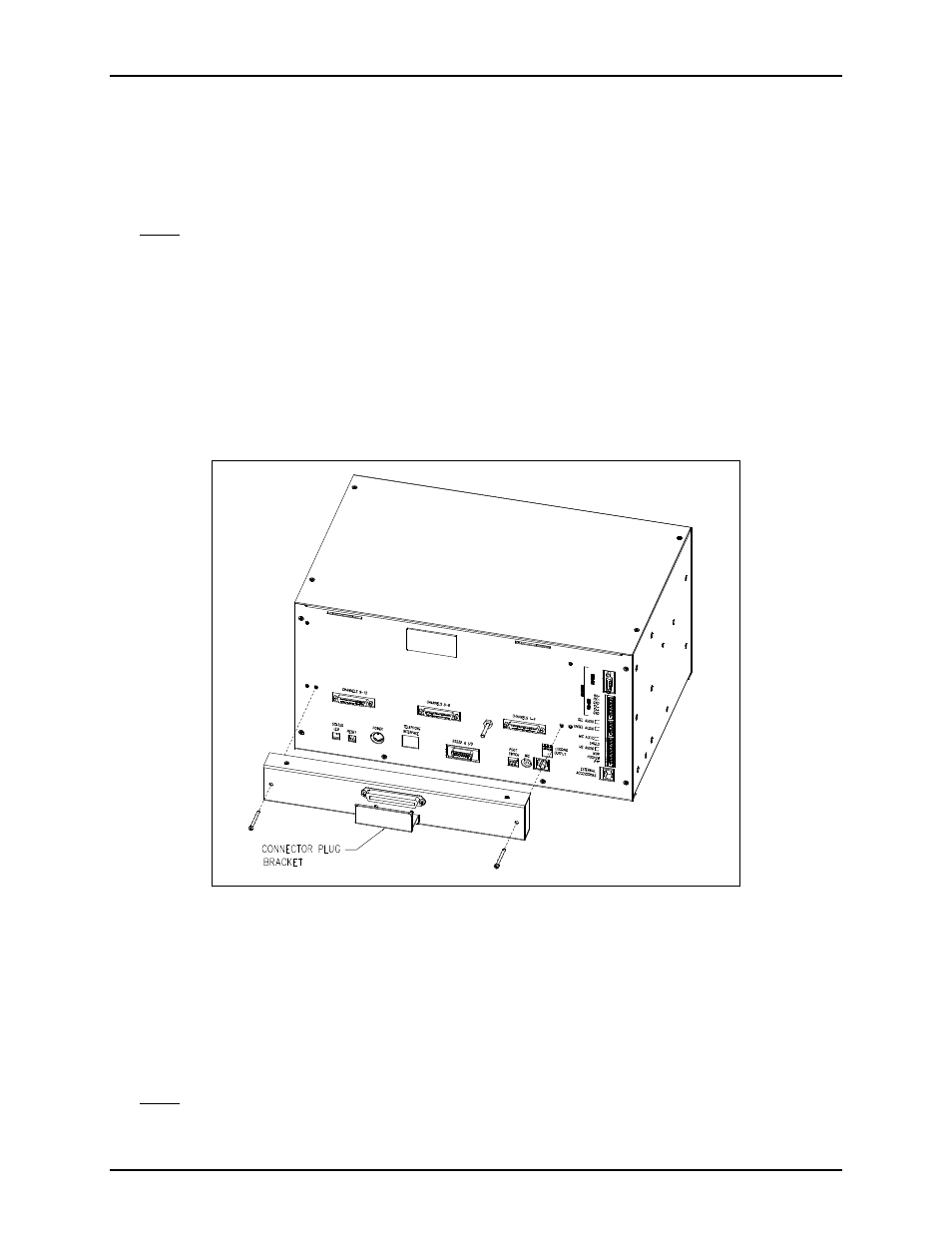
3. Secure the Telco Interface with the supplied #6-32 screws shown in Figure 3 or Figure 4, tightening
them until the Telco unit is snug against the rear panel or the Supervisor panel.
4. Plug one end of a standard DB50 connector plug into the single 50-pin Telco connector and terminate
the other end to an applicable punch block. Place the connector plug bracket over the 50-pin
connector and secure with two screws. The bracket secures the connector to the Telco interface.
5. Reattach the necessary accessory cables and reconnect the power.
Note: The Supervisor unit input connectors and output connectors can each have a separate Telco
Interface unit attached.
Figure 3.