GAI-Tronics XCP0040A 4-Channel E&M Control Kit User Manual
Page 2
Pub. 43003-015B
Model XCP0040A 4-Channel E&M Control Kit
Page: 2 of 2
11/02
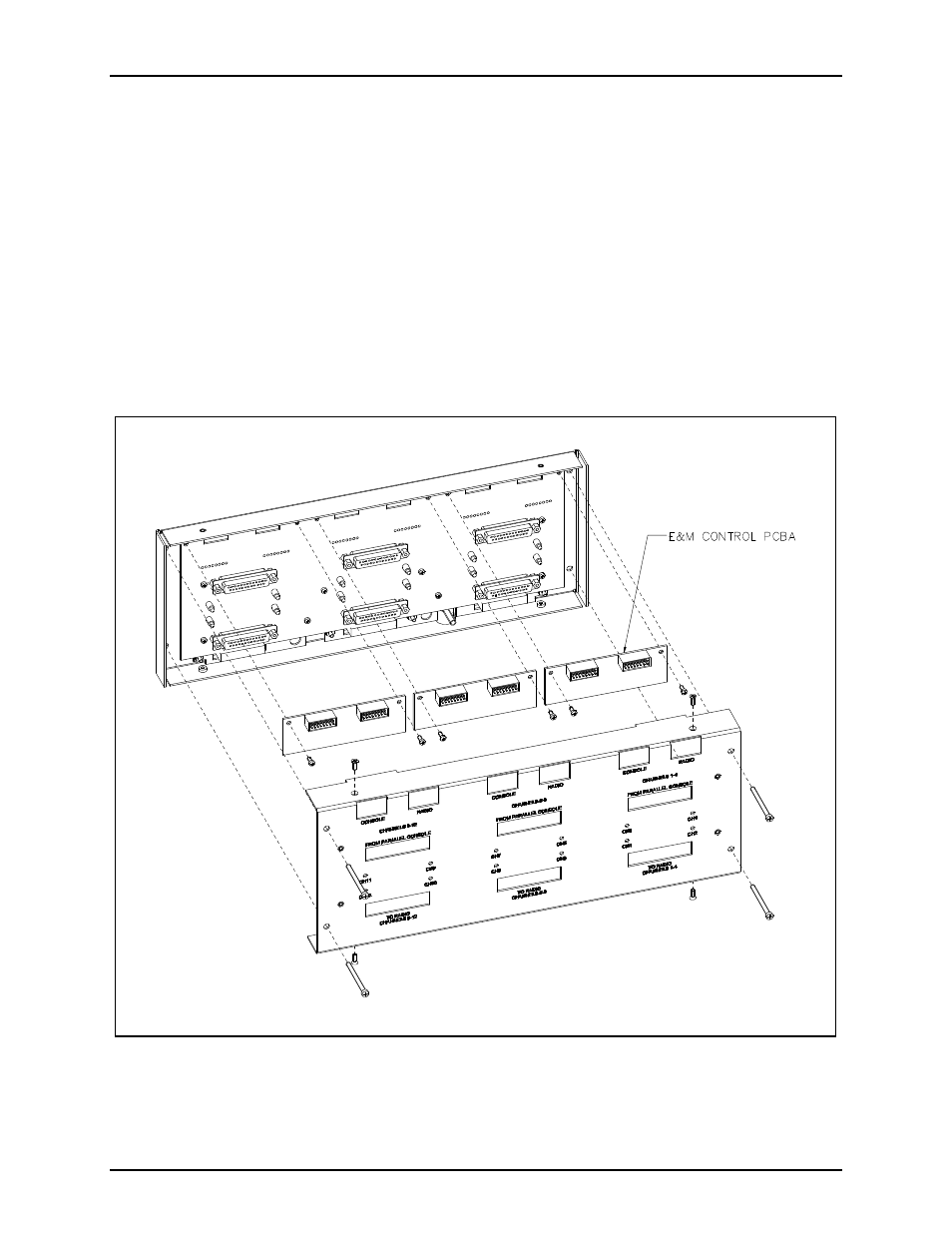
4. Remove the two #4-40 screws on the top right of the Supervisory PCBA to add E&M Control to
channels 1 through 4, on the top middle for channels 5 through 8, and on the top left for channels 9
through 12. Refer to the silk screen labeling on the Supervisory cover for clarification.
5. Attach the E&M board to the CES PCBA in the Supervisory unit by inserting the connector pins
through the holes in the board as shown in Figure 1.
6. Replace the #4-40 screws that you originally removed from the CES board in order to secure the
E&M Control PCBA. Insert the screws through both boards and tighten until snug.
7. Replace the Supervisory unit’s cover along with the four #6
×
32 screws and the four #4
×
40 screws,
and reattach all cables. Reconnect the power.
8. Refer to the CARD Suite Software (XAC1000A) for the specific programming instructions for
reconfiguration.
Figure 1.