GAI-Tronics XCP0060A External Enhanced Full Duplex Phone Interface Field Kit User Manual
Page 3
Pub. 43003-017C
Model XCP0060A External Full Duplex Phone Interface Kit
Page: 3 of 5
11/02
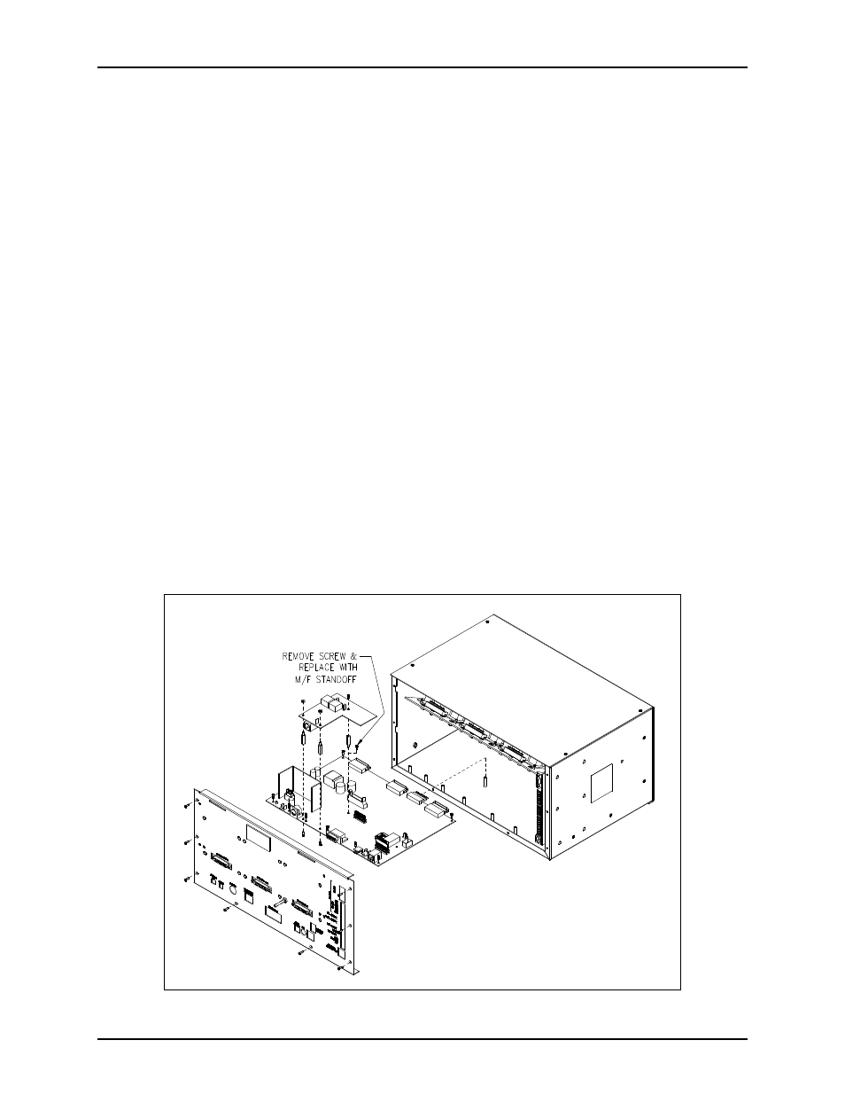
5. Remove the 4 screws attaching the mounting plate to the base. This allows you to remove the
mounting plate giving you access to the main control PCBA. See Figure 2.
6. Remove the screw in the center of the main control PCBA. Screw in one of the supplied #4-40
male/female standoffs. See Figure 1.
7. Attach the remaining two standoffs in the two open holes highlighted by circles on the main control
PCBA. Place the threaded side through the holes and attach the supplied #4-40 nuts to the underside.
See Figure 1.
8. Place the CTH PCBA on the standoffs and attach with the supplied #4-40 screws. The J13 connector
plugs into the P13 connector on the main control PCBA. See Figure 1.
9. Attach the supplied ground cable to the ground screw located on the rear panel. Attach the other end
to the quick-disconnect on the CTH PCBA.
10. After the PCBA has been properly mounted, you may reassemble the console by reversing the
disassembly procedure. Verify that all CSD-to-main board ribbon cables are properly positioned into
their protective guides and connected to their respective main board connectors.
ICP9000 Navigator Series MCU
1. Disconnect power from the ICP9000 Navigator Series MCU and remove all attached cables from the
rear cover.
2. Remove the 8 screws securing the rear panel. Gently pull the rear cover from the housing and
disconnect the ribbon cables (SLV-CBL-P) attached to the surge suppression PCBA. Lay the rear
panel flat. See Figure 3. (Do not install the phone PCBA at this point.)
Figure 3.