GAI-Tronics XCP0300A Navigator Upgrade Kit User Manual
Page 3
Pub. 43003-031D
Model XCP0300A Navigator Upgrade Kit
Page: 3 of
3
f:\radio products-draft\gtc 43003\43003-031d\43003-031d.doc
12/10
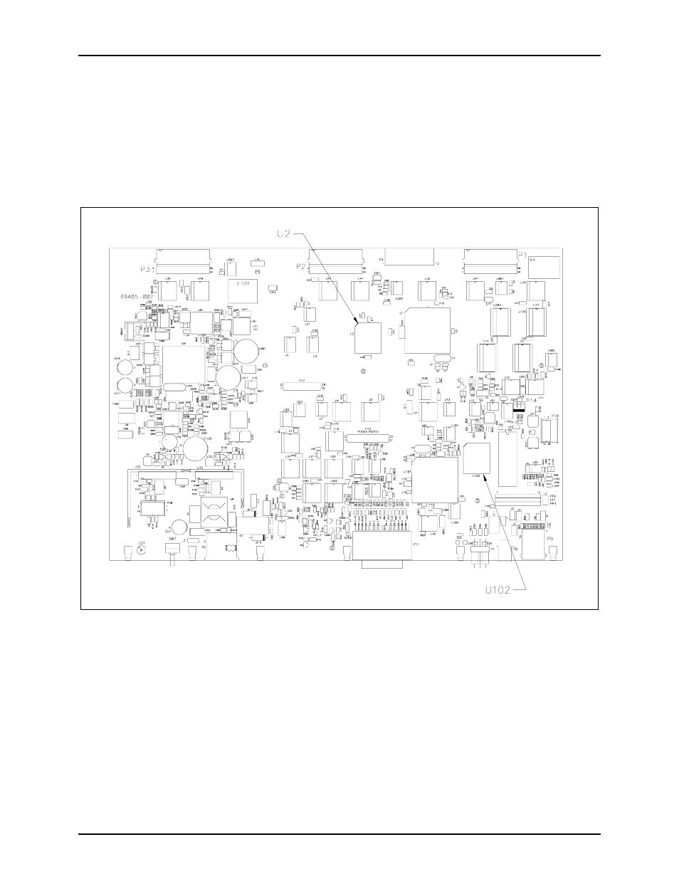
8. On the main PCBA locate U2 EPROM socket and extract the EPROM. Refer to Figure 2.
9. Replace it with the Master EPROM (MAST**) provided in this kit taking care to observe the
direction indicated on the socket of the EPROM. Ensure that the chip is properly seated in the socket.
10. Next locate U102 EPROM socket and extract the EPROM.
11. Replace it with the Host EPROM (HNAV**) provided in this kit, taking care to observe the direction
indicated on the socket of the EPROM. Ensure that the chip is properly seated in the socket.
Figure 2. Main (69405-002) PCBA
12. Turn the MCU enclosure on its side so that the ICP9000 display extender PCBA (69509-001) is
sitting up right. On display extender PCBA locate U4 EPROM socket and extract the EPROM.
13. Replace it with the Navigator EPROM (49072-***) provided in this kit taking care to observe the
direction indicated on the socket of the EPROM. Ensure that the chip is properly seated in the socket.
14. After replacing the EPROMs, you can reassemble the desktop console by reversing the disassembly
procedure. Verify that all of the cables have been reconnected back to their respective connectors as
you proceed through the steps.