GAI-Tronics SPK100 Solar Panel Interface Kit User Manual
Page 2
Pub. 43003-043A
M
ODEL
SPK100 S
OLAR
I
NTERFACE
K
IT
Page:
2 of 3
d:\radio products-current release\43003\43003-043a\43003-043a.doc
05/06
3. Install the mounting kit to the desired surface. If surface mounting, two lag screws or bolts are
required. If pole mounting, the included U-bolts (up to 4-inch diameter) are required.
4. Route the cable attached to the panel into the Model CB193-xxx, CB194-xxx, or CB195 RF Call
Box.
Installing the Charge Regulator Module and Interconnection
1. Install the charge regulator module into the rear of the enclosure using the #6-32
× 0.250-inch screws
and mounting plate provided. Refer to Figure 2 for the location of the charge regulator on each of the
RF Call Box models. The charge regulator can be mounted directly to the back box for Model
CB195-xxx. For Models CB193-xxx and CB194-xxx, use the supplied mounting plate to attach the
charge regulator.
2. Install the temperature sensor from the regulator module to the top of the battery using the
adhesive-backed foam provided. See Figure 2 for the location within the appropriate call box model.
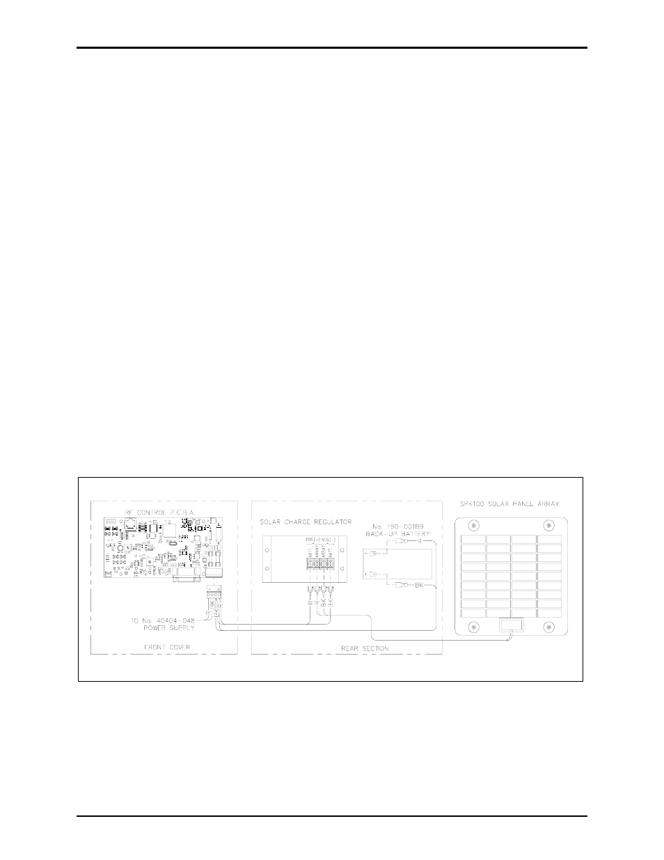
3. Locate the 8-inch wire harness (black/red wires). Connect the lugged end of the red wire to battery
positive (+) terminal point on the regulator module. Connect the lugged end of the black wire to the
battery negative (-) terminal point of the regulator module.
4. The PCBA is located on the front cover of the enclosure. Connect the bare lead of the red wire to pin
1 of the PCBA’s TB1 connector. Connect the bare lead of the black wire to pin 2 of TB1. Refer to
Figure 1 for location on the PCBA.
5. Run the solar array wires into the enclosure and attach both the positive (red wire) and negative
(black wire) to the regulator module. The red wire should be attached to the “array positive” terminal
and the black wire should be attached to the “array negative” terminal. Dress the wires to avoid
contact with the internal antenna or external antenna cable. Refer to Figure 1 below.
Figure 1. Solar Panel Wiring Diagram