Installation, Attaching the mounting bracket, Wiring connections – GAI-Tronics 190-3170K RF Call Box Adapter Kit for Kenwood Radio 3170 User Manual
Page 2
Pub. 43003-044B
M
ODEL
190-3170K
RF
C
ALL
B
OX
A
DAPTER
K
IT FOR
K
ENWOOD
170
S
ERIES
P
ORTABLE
R
ADIO
Page:
2 of 4
\\s_eng\gtcproddocs\radio products-current release\43003\43003-044b\43003-044b.doc
02/07
Installation
Attaching the Mounting Bracket
1. Remove the four screws from the front of the enclosure using a Torx T-25 security bit. Open the
front cover to the left and pull straight out until the hinge pins separate from the rear section. Set the
front cover of the enclosure aside.
N
OTE
: The Model CB195-003 uses six mounting screws and does not have hinges on the front
panel.
2. Loop the Velcro strap through the slots on the mounting bracket. Attach the supplied rubber
bump-ons to the upper right and left corners of the bracket.
3. Attach the mounting bracket to the lower left enclosure embossments as shown in Figure 2.
N
OTE
: In Model CB195-003, discard the bracket and loop the Velcro strap directly into the back box
slots.
Programming the Kenwood 170 Series Radio
Refer to the RF Call Box Installation and Operation Manual, Pub. 43004-031, for complete programming
instructions. Pre-program the portable prior to installing into the call box.
Wiring Connections
4. Connect the battery eliminator to the customer-supplied Kenwood radio. Secure the radio using the
Velcro strap.
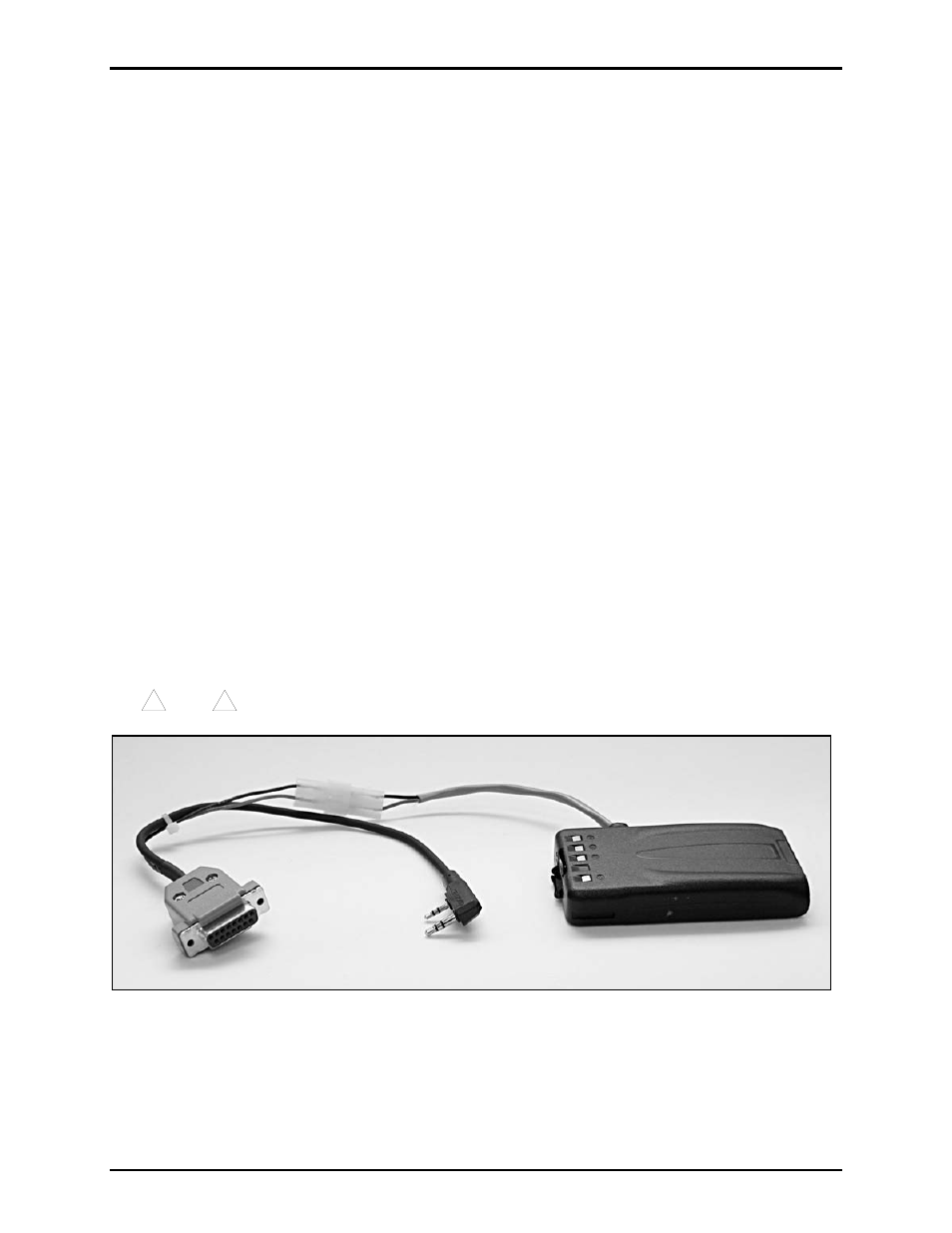
5. Connect the DB15 side of the interface cable to the RF control PCBA (located inside the front cover
of the call box). Plug the dual 2.5/3.5-mm audio plug into the socket of the Kenwood radio. Connect
the battery eliminator plug and the interface cable receptacle. See Figure 1.
!
!
Note
Observe polarity. Red to red and black to black.
Figure 1. Cable Assembly