Geist Water Sensor Kit User Manual
Page 3
3
Water Sensor Kit quick-start guide (rev.140729A-IT)
Geist, Lincoln, Nebraska, USA — geistglobal.com
C
C
1
2
3
C
1
C
2
C
3
C
4
ANALOG INPUTS
Dry Contact / 0-5VDC
C 1 C 2 C 3 C 4 C 5 C 6
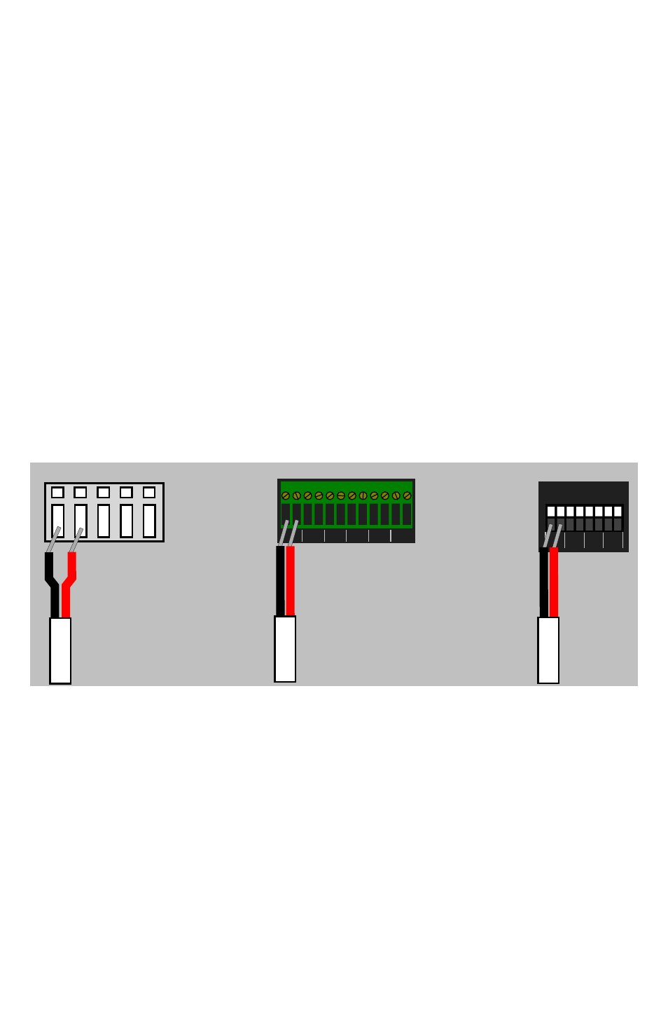
RSE-style terminals
GRSO-style terminals
GBB-style terminals
CONNECTING THE WATER SENSOR TO A GEIST
ENVIRONMENTAL MONITORING UNIT:
The Water Sensor is directly compatible with any model of RSE, GRSO, or GBB-series
monitoring unit which has analog-sensor inputs. Models which do not have built-in analog
inputs, such as the RSMINI or GBB15, will require the use of an appropriately-
programmed Analog-to-Digital converter (sold separately) to use the water sensor. (An
A-to-D converter can also be used if all of your unit’s analog inputs are already occupied
with other sensors. Information on how to set up and use the water sensor with the
analog-to-digital converters can be found in the user guide for that device.)
The red and black wires from the sensor are connected to the analog-input terminals as
shown here. (Different models have different terminal-block styles.) Note that since the
sensor is a simple conductivity (resistance-detecting) sensor, with no inherent signal
voltage or polarity of its own, the actual order of the wires is not important; however, for
consistency, black should be connected to the “C” terminal and red should go to the
corresponding numbered terminal.