Sensor configuration and alarm-threshold settings – Geist Water Sensor Kit User Manual
Page 4
4
Water Sensor Kit quick-start guide (rev.140729A-IT)
Geist, Lincoln, Nebraska, USA — geistglobal.com
SENSOR CONFIGURATION AND ALARM-THRESHOLD SETTINGS:
Unlike digital sensors such as the GTHD Temperature/Humidity sensor, analog sensors do not
automatically show up in the monitoring unit’s web page when connected. Since there is no
exchange of digital data between the unit and sensor, the unit has no way to know whether a sensor
has been connected to the analog input or not. Therefore, sensors connected to the analog inputs need
to be configured manually. (The following screenshots are taken from a GBB100, but the process
for configuring other models is essentially the same.)
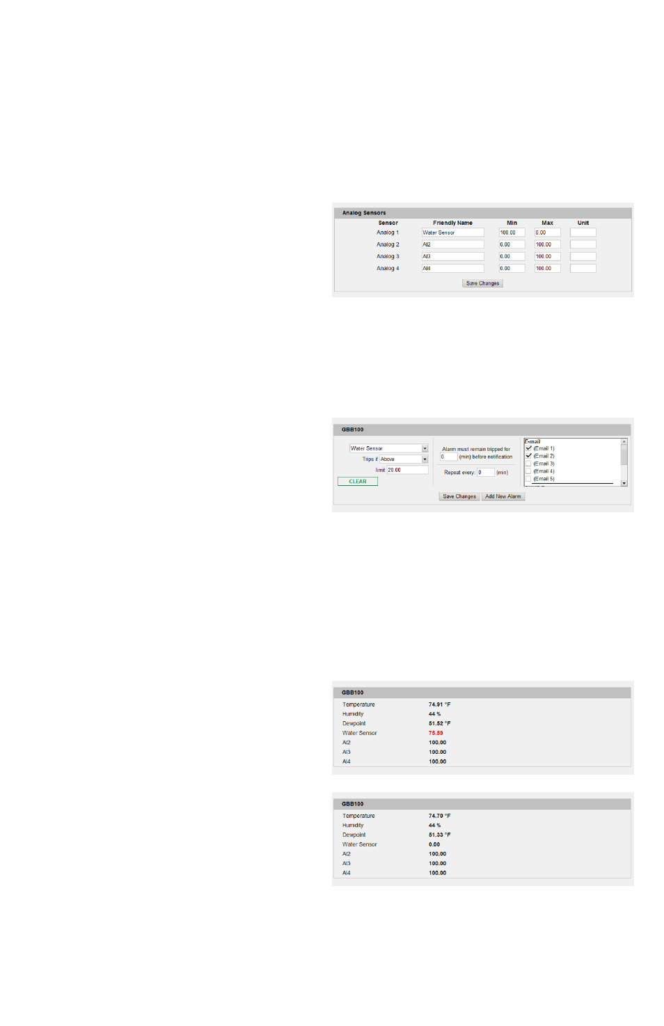
First, click the Display tab, then locate the
Analog Sensors setting block at the bottom,
similar to the one shown here. Change the
Friendly Name of the analog input which
corresponds to the one you connected the water
sensor’s wires to as above, set Min to 100 and
Max to 0, then click Save Changes. (Unit can be
left at its default value.) This will “reverse” the usual scaling of the analog inputs, so that a dry sensor
will read 0 and the reading will increase towards 100 as the surface under the sensor gets wet. (If
Min and Max were left at their defaults, the sensor would start with a high number when dry and
decrease towards 0 as the sensor got wet, which is the opposite of what most users would expect to
see.)
Next, click the Alarms tab. Analog sensors are
considered part of the unit’s own sensor package,
so they will be listed along with the rest of the
unit’s internal sensors, not as separate devices of
their own. Click the Add New Alarm button for
the monitoring unit’s internal sensors, then
choose the analog input whose name corresponds
to the one you set in the prior step (“Water Sensor”, in this example) from the drop-down box.
Normally, the sensor should show a value close to 0 with the above settings. However, depending
on the surface the sensor is sitting on, the “dry” value may be a little above 0 if the surface itself is
slightly conductive. Setting a trip theshold of Trips if: Above and Limit: 20 is a good place to start;
if you notice the sensor false-triggering too often, increase the limit until the false triggers stop.
(Cleaning the sensor and underlying surface may also help stop false triggering.) Select any other
actions (delay, repeat, e-mail recipients, etc.) as desired, then click Save Changes.
Test the configuration by clicking on the Sensors
or Overview page, then put the sensor on a wet
surface. The reading should turn red, indicating
a tripped alarm, displaying a value well above
the “20” threshold, as shown here. (If this
doesn’t happen within a few moments, hit [F5] to
refresh the web page.)
Dry the sensor, wait a few moments, then refresh
the web page. The reading should turn black
(“no alarm”), with a reading close to 0 again.