Groth 7618 User Manual
Page 4
Page 4 of 16
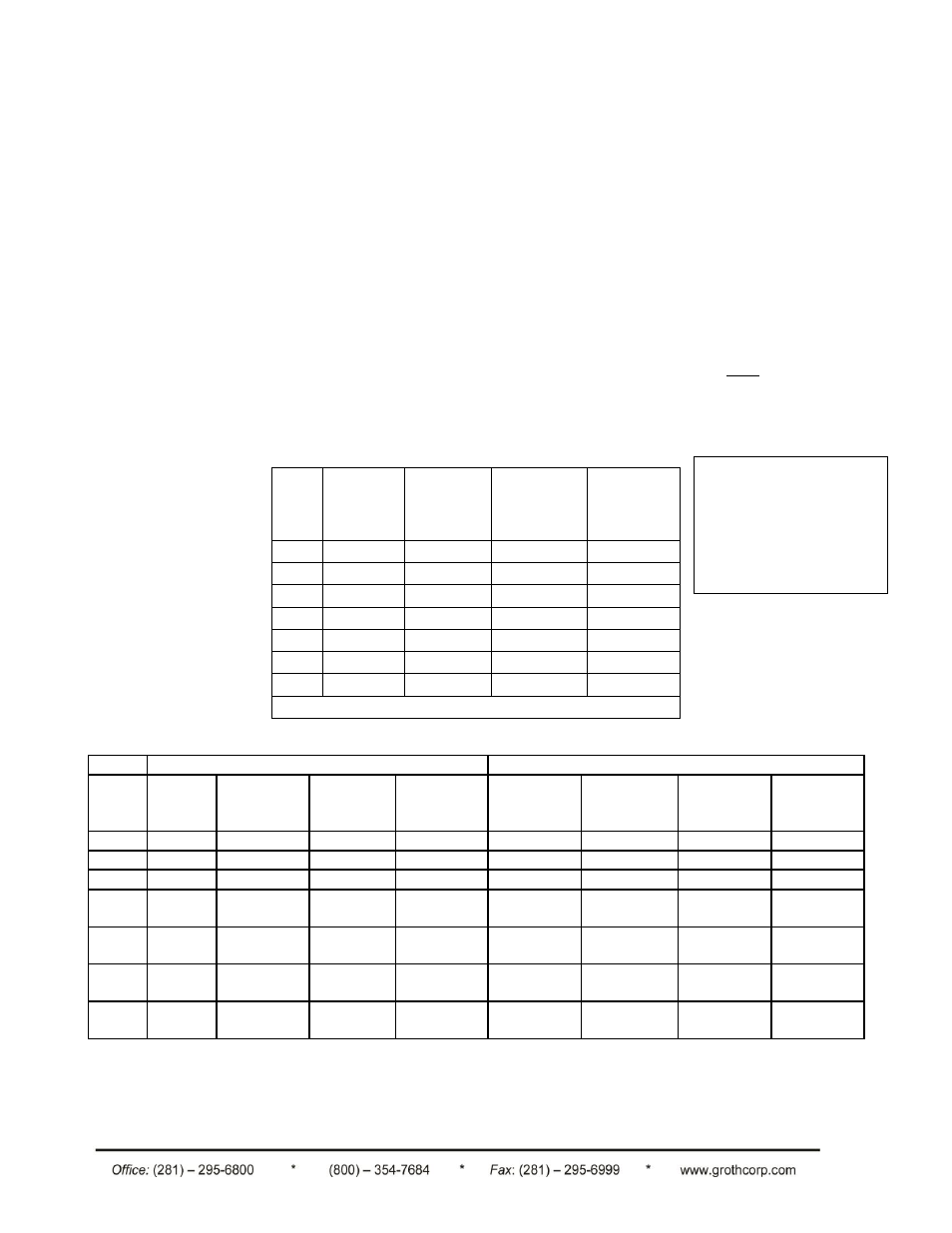
The MAWP is different
from the approved pre-
ignition pressure.
Consult the factory for
pre-ignition pressure
limits for your
installation.
II. INSPECTION AND INSTALLATION
All Groth Corporation's flame arresters are bi-directional and the installation on a tank or piping system
depends to a great extent on the design of the system. The Model 7618 is recommended for vertical
installation in closed piping systems or venting to atmosphere. If a Model 7618 is installed in a
horizontal line, it should be equipped with drain ports for removal of condensation from the housing.
WARNING: Do not pipe both drainage connections to a common line as
this can provide a passage for flame to by-pass the flame arrester element.
The Model 7628 is designed for either vertical or horizontal installation.
These series of flame arresters have 150# ANSI PN 10 OR PN 16 flange drilling compatibility, [30" &
36" model 7618 & 7628 have API 650 drilling], and are pneumatically tested to 15 PSIG at the factory.
Follow the guidelines listed in Table 2 for flange make-up torque. The arresters are NOT rated for full
flange pressure and do not require high bolting torque. Recommended torque values are
based on
pressures [MAWP] in Table 1. Consult factory for higher pressure applications.
Note:
TABLE 1: FLAME ARRESTER MAWP [PSIG (kPa)]
Size
Model
7618
Alum
Model
7618
CS/SS
Model
7628 Alum
Model
7628
CS/SS
2"
50 (345)
100 (690)
150 (1034)
275 (1965)
3"
50 (345)
100 (690)
140 (965)
275 (1965)
4"
50 (345)
100 (690)
140 (965)
275 (1965)
6"
50 (345)
100 (690)
140 (965)
275 (1965)
8"
50 (345)
100 (690)
90 (620)
200 (1379)
10"
50 (345)
100 (690)
75 (482)
150 (1034)
12"
50 (345)
100 (690)
75 (482)
150 (1034)
Sizes > 12" (7618 & 7628): MAWP = 15 PSIG
TABLE 2: BOLT TORQUE [ft-lbs (Nm)]
Flange*
Housing
Size
Raised
Face
Steel
Raised
Face
Aluminum
Flat
Face
Steel
Flat Face
Aluminum
Model
Steel 7618
Model
Steel 7628
Aluminum
Housing
7618
Aluminum
Housing
7628
2"
60 (82)
35 (47)
60 (82)
50 (68)
60 (82)
40 (54)
50 (68)
35 (47)
3"
60 (82)
35 (47)
60 (82)
50 (68)
60 (82)
40 (54)
50 (68)
35 (47)
4"
60 (82)
35 (47)
60 (82)
50 (68)
60 (82)
40 (54)
50 (68)
35 (47)
6"
105
(143)
60 (81)
105 (143)
90 (122)
105 (143)
105 (143)
90 (122)
90 (122)
8"
105
(143)
60 (81)
105 (143)
90 (122)
105 (143)
105 (143)
90 (122)
90 (122)
10"
140
(190)
100 (136)
170 (231)
140 (190)
170 (231)
220 (300)
140 (190)
170 (231)
12"
140
(190)
100 (136)
170 (231)
140 (190)
170 (231)
220 (300)
140 (190)
170 (231)
*Torque values are for reference only and based on a nitrile binder synthetic gasket,
1/16" thick and unlubricated threads.