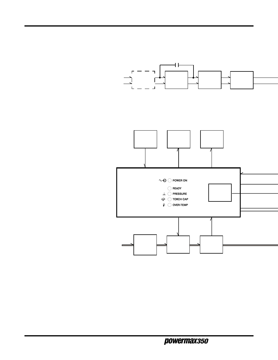
Functional block diagram, 115/230 volt, Figure 3-2.1, Functional block diagram, 115/230 volt unit – Hypertherm Powermax350 Service Manual User Manual
Page 28: Service manual, Aintenance
Service Manual
3-4
M
AINTENANCE
115 or 230 VAC
1 Ø Line Input
Power
Line Input
Filter FL1
(CE Units)
Input
Resistor
R2
Power
Switch
S1
CR6
1
Input Filter FL1 (CE units only)
Provides input power noise filtering.
2
Power Switch S1
Provides on/off control of power to
main transformer T1.
3
Input Voltage Selector Switch S2
Connects primary of main transformer
T1 for 115 or 230 VAC operation.
4
Fan Motor FM
Provides cooling of internal components.
5
Main Transformer T1
Supplies power to output circuit, power
control board PC1, safety control board
PC2, and fan motor FM.
6
Integrated Rectifier SR1
Changes AC output from T1 to full-wave
rectified DC.
7
Power Control Board PC1
Supplies and regulates cutting current
to torch. Also provides some timing and
control functions.
8
Safety Control Board PC2
Provides timing and control functions,
monitors safety interlocks and provides
isolation from power circuitry. Also
contains power, ready and trouble LEDs.
9
Output Control R6
Selects cutting output level.
10
Thermostat TP1
If unit overheats, TP1 opens stopping
cutting output. TP1 is located inside T1.
11
Power-Up Delay Relay CR6,
Input Resistor R2
During power-up (2-3 seconds), R2 limits
inrush current to T1. CR6 shorts out R2
after power up delay and keeps R2
shorted out while the unit is operating.
12
Contactor Control Relay CR7
Connects main transformer T1 secondary
output power to integrated rectifier SR1.
13
Air Filter/Regulator
Filters and regulates pressure of input air
supply.
14
Air Valve GS1
Allows airflow for pilot arc, cutting and
postflow.
15
Air Pressure Switch S3
Provides signal to PC2 to shut down unit
if air pressure is to low.
Output
Control
R6
Safety
Control Board
PC2
Air
Valve
GS1
Air Pressure
Switch
S3
Power-Up
Delay
Relay CR6
Contactor
Control
Relay CR7
Thermostat
TP1
Input Air Supply
70-120 psi
(4.8-8.3 bar)
1
11
2
Input Voltage
Selector
Switch S2
3
8
9
10
11
12
14
15
Air Filter/
Regulator
60 psi
(4.1bar)
13
7-98