Test 5 – inverter igbt (q6) and pfc igbt (q7), Powermax1250, Maintenance 3-26 – Hypertherm Powermax1250 Service Manual User Manual
Page 59: Service manual
Advertising
MAINTENANCE
3-26
powermax1250
Service Manual
4
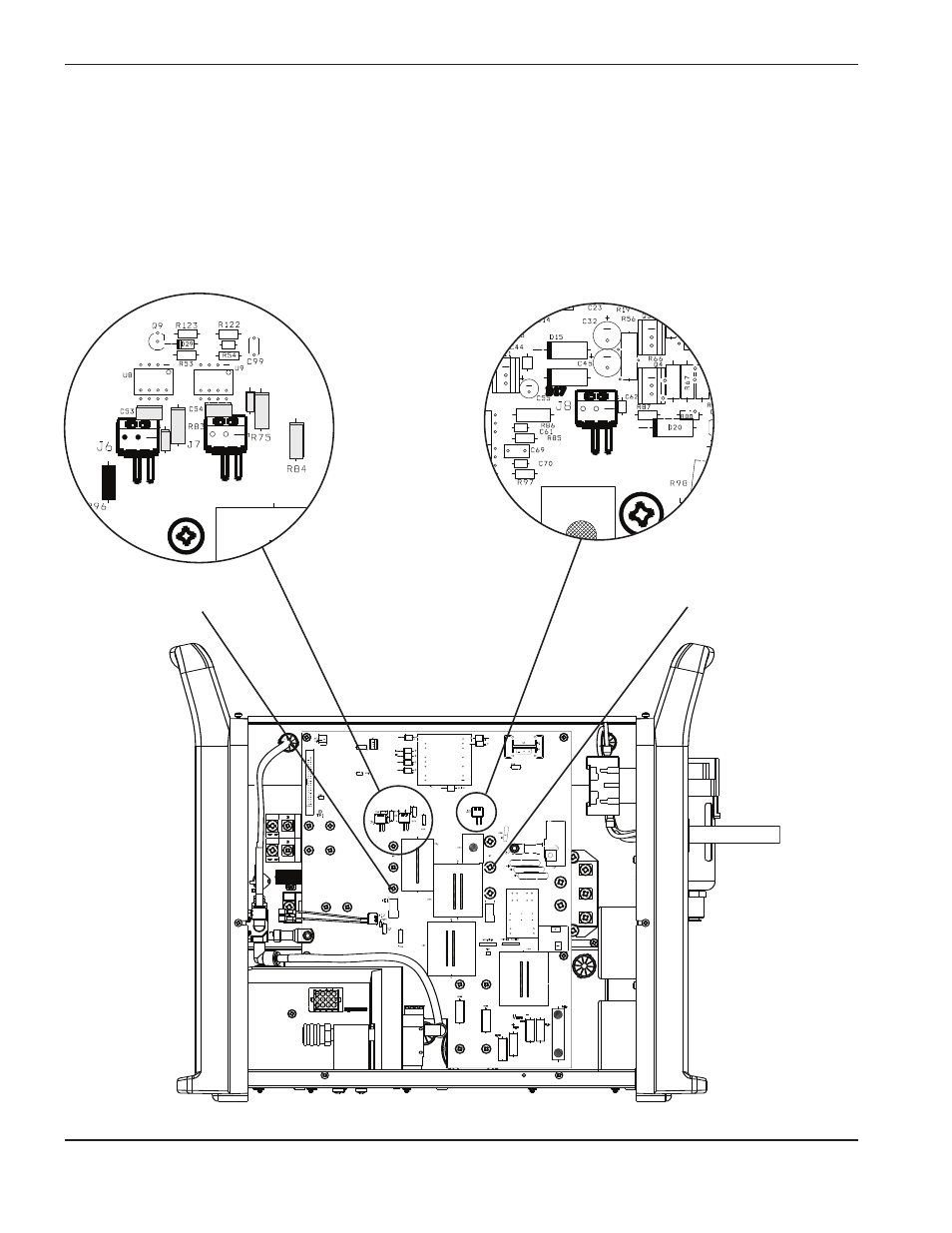
Test 5 – inverter IGBT (Q6) and PFC IGBT (Q7)
• Check the resistance of the gate-drive circuit.
• If values are not ±25% of the values shown below, replace the power board (PCB2) and the appropriate
IGBT.
• If values are correct, check both IGBTs with an IGBT tester. If one IGBT fails, replace the power board
(PCB2) and the failed IGBT.
80
C100
80
C100
Inverter IGBT (Q6)
PFC IGBT (Q7)
o
o
o
o
R
6
5
R
8
2
Inverter
R82 = 994
Ω
R83 = 6.1
Ω
R65 = 995
Ω
R75 = 6.1
Ω
R84 = 10.4
Ω
R96 = .4
Ω
PFC
R87 = 994
Ω
R56 = 4.1
Ω
R98 = 1
Ω
Advertising
See also other documents in the category Hypertherm Equipment:
- EDGE Pro Ti Shape Cutting Control Rev.2 (288 pages)
- 80669J Rev.3 (304 pages)
- HD3070 Plasma Arc Cutting System w/ Manual Gas Console (281 pages)
- MAXPRO200 Rev.2 (294 pages)
- MicroEDGE Pro Shape Cutting Control Rev.2 (182 pages)
- Powermax1650 (317 pages)
- HPR260 Auto Gas Preventive Maintenance Program Rev.4 (288 pages)
- Shape Cutting Control (66 pages)
- PHC Sensor (58 pages)
- HTA Rev 6.00 Operators Manual (212 pages)
- HTA Rev 7.00 Install Guide (242 pages)
- THC Control Board Replacement (13 pages)
- THC Plasma Interfacer Upgrade (9 pages)
- THC X-Y Table Product Configuration (20 pages)
- D845GERG2 (128 pages)
- MRT2 (64 pages)
- MRT (98 pages)
- Duramax Hyamp Long Handheld Torches (92 pages)
- Duramax Hyamp Robotic Torch (74 pages)
- HyIntensity Fiber Laser Rev.3 (240 pages)
- PCBS-0124 (70 pages)
- SuperMicro 370SBA 533Mhz (90 pages)
- LR2075 (56 pages)
- Phoenix 8.0 (585 pages)
- LH2125 (60 pages)
- HD3070 w/ Automatic Gas (35 pages)
- HD3070 w/Manual Gas (43 pages)
- HD4070 Rev.8 (278 pages)
- HD4070 Product Configuration (88 pages)
- HPR800XD Manual Gas Preventive Maintenance Program Rev.1 (32 pages)
- HPR800XD Manual Gas Preventive Maintenance Program Rev.1 (33 pages)
- HPR800XD Manual Gas Rev.2 (368 pages)
- HPRXD Short Torch with Integrated Lead Rev.1 (30 pages)
- HT4001 (59 pages)
- DuraChill 5 HP Air-Cooled Chiller For Hypertherm (29 pages)
- HT4001 Air Injected Water Muffler System (40 pages)
- H601 Power Supplies (62 pages)
- MAX200 Remote Switch (9 pages)
- HT4100 Plasma Arc Cutting System Operating (50 pages)
- HT4001 Plasma Arc Cutting System (259 pages)
- HSD130 HySpeed Plasma (233 pages)
- HySpeed HT2000 Plasma Arc Cutting System Rev.7 (53 pages)
- HySpeed HT2000 Plasma Arc Cutting System Rev.27 (289 pages)
- MAX200 Water Muffler (39 pages)
- HT2000LHF Product Configuration (23 pages)