J5: spi debug tools port, Factory use only), J8: power led – IBASE MI941 User Manual
Page 21: J9: system function connector, Pin # signal name 7 +5v 8 +5vsb
INSTALLATIONS
J5: SPI Debug Tools Port
(Factory use only)
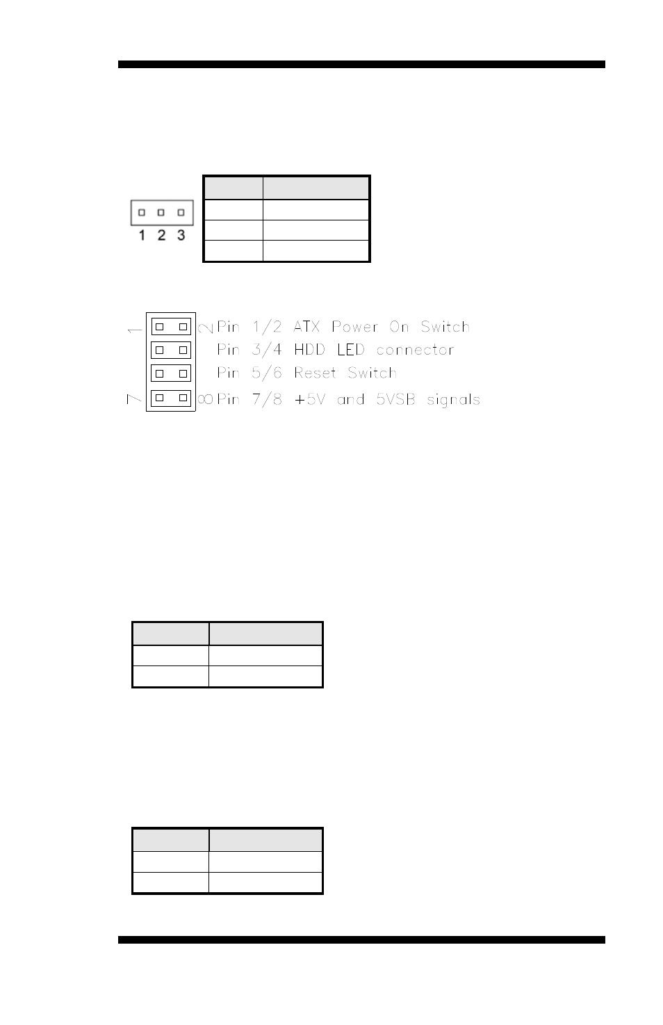
J8: Power LED
The power LED indicates the status of the main power switch.
Pin #
Signal Name
1 Power
LED
2 No
connect
3 Ground
J9: System Function Connector
ATX Power ON Switch: Pins 1 and 2
This 2-pin connector is an “ATX Power Supply On/Off Switch” on the
system that connects to the power switch on the case. When pressed, the
power switch will force the system to power on. When pressed again, it
will force the system to power off.
Hard Disk Drive LED Connector: Pins 3 and 4
This connector connects to the hard drive activity LED on control panel.
This LED will flash when the HDD is being accessed.
Pin #
Signal Name
4 HDD
Active
3 5V
Reset Switch: Pins 5 and 6
The reset switch allows the user to reset the system without turning the
main power switch off and then on again. Orientation is not required
when making a connection to this header.
+5V and 5VSB Signals: Pins 7 and 8
Pin #
Signal Name
7 +5V
8 +5VSB
MI941 User’s Manual
17