IBASE MB838 User Manual
Page 17
INSTALLATIONS
17
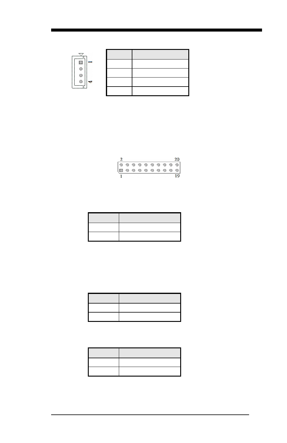
J1, J13: Power Connector, Pitch 2.54mm
Pin #
Signal Name
1
+5V
2
GND
3
GND
4
+12V
J2: 7-pin SATA connector
J3: System Function Connector
J3 provides connectors for system indicators that provide light indication
of the computer activities and switches to change the computer status. J13
is a 20-pin header that provides interfaces for the following functions
Pin 1, 2: Speaker
This connector provides an interface to a speaker for audio tone
generation. An 8-ohm speaker is recommended.
Pin #
Signal Name
1
+5V
2
GND
Pin 13, 14: ATX Power ON Switch
This 2-pin connector is an “ATX Power Supply On/Off Switch” on
the system that connects to the power switch on the case. When
pressed, the power switch will force the system to power on. When
pressed again, it will force the system to power off.
Pin #
Signal Name
13
GND
14
Power_ON
Pin 15, 16: Power LED
The power LED indicates the status of the main power switch.
Pin #
Signal Name
15
+5V
16
GND