Installations – IBASE MB838 User Manual
Page 7
INSTALLATIONS
7
Fan
Connector
Three 4-pin smart fan connectors
Smart Fan
Control
The active temperature may be adjusted based on system thermal test result
Active
Temperature
Tolerance
Default Smart Fan
Enable or Disable
CPU Fan
50
+/- 3
Enable
System Fan
50
+/- 3
Enable
RTC
Rangeley built-in RTC with on-board lithium battery & holder
Expansion
Slot
(Golden
Finger)
#1: PCI-e x8, for IP332
#2: PCI-e x4, for IP334
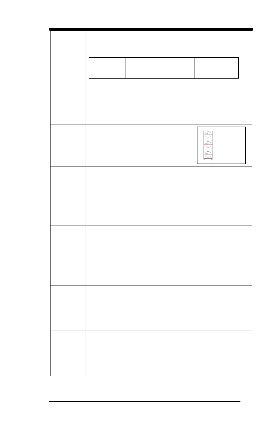
Front Panel
Function LED
#1 LED: Power
(Green = Power On, Off= No Power)
#2 LED: Bypass or Status 2 (Pin header control)
Bypass: Green = LAN 1-2 or 3-4 Bypass,
Off = LAN Normal
#3 LED: Status 1 (GPIO control, Yellow / Red)
LCM
Optional, iIO 2x16 characters LCM (COM2)
Front Panel
Buttons &
Connector
Four RJ-45 connectors for Eth1~4 with LEDs
USB 2.0 x2
RJ-45 (for console, COM1)
Three LEDs for Power, Bypass & Status
Factory Mode Restore Reset Switch
Rear I/O
interface
PSU AC inlet
1x Slot Opening
Jumper /
Pin Header /
Switch
AT or ATX mode selection jumper
ATX mode power on / off pin header
HDD active LED pin header
System Reset pin header
Clear CMOS
Power
Connector
24-pin ATX standard (connected to system power supply)
2-pin 12V DC-In (connected to external power adapter)
TPM
TPM 1.2 (INFINEON SLB9655TT1.2)
Watchdog
Timer
Yes (256 segments, 0, 1, 2…255 sec/min)
Operating
Temperature
0
C ~ 60
C
Storage
Temperature
-20
C ~ 80
C
Operational
Humidity
10% ~ 90% Relative Humidity (non-condensing)
RoHS
Compliant
Yes
Dimensions
203 mm x 180 mm
Status 1
Bypass
Power