IBASE MB839 User Manual
Page 17
Advertising
INSTALLATIONS
MB839 Series User’s Manual
11
J3: MCU Update (Factory use only)
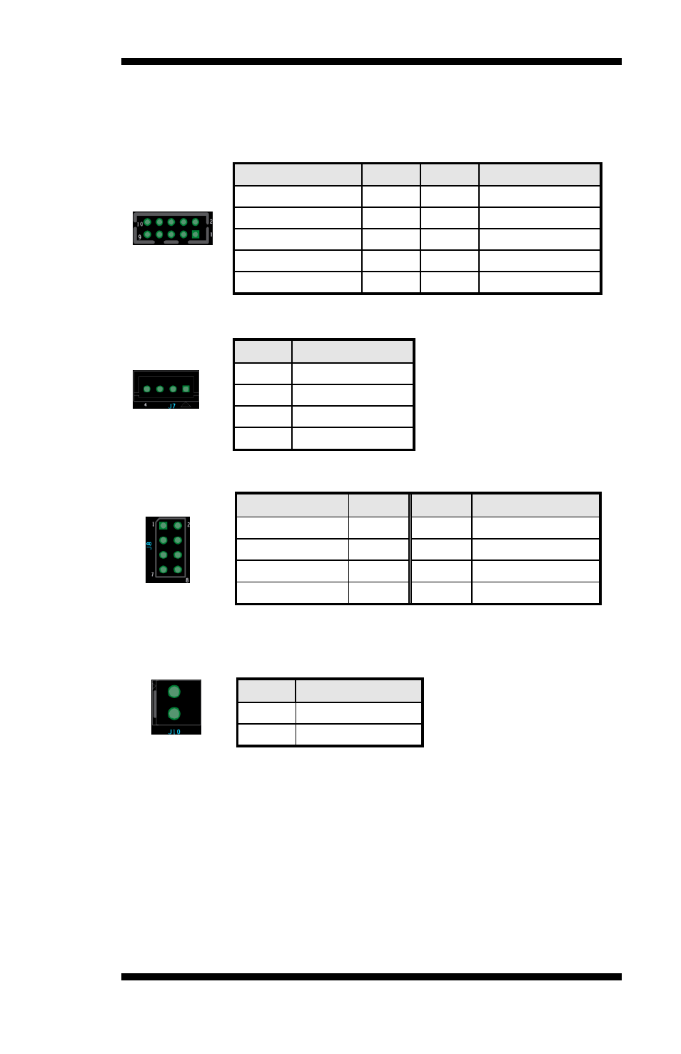
J4: Serial Port (COM2)
Signal Name
Pin #
Pin #
Signal Name
DCD#
1
6
DSR#
SIN
2
7
RTS#
SOUT
3
8
CTS#
DTR#
4
9
RI#
GND
5
J7: SATA Power Connector
Pin #
Signal Name
1
+5V
2
Ground
3
Ground
4
+12V
J8 : USB 2.0 Pin Header
Signal Name
Pin #
Pin #
Signal Name
NC
1
2
GND
NC
3
4
D+
NC
5
6
D-
GND
7
8
+5V
J10: AT_12V Connector
DC-in internal connector supports +12V.
Remarks: Do not connect CN12 and J10 at the same time.
Pin #
Signal Name
1
+12V
2
Ground
Advertising